Transmission Design Considerations of Cam Mechanisms
Terminology:
Input Transmission: the transmission components from the Power-Source (usually an electric motor) to, most often, a cam on a cam-shaft.
Output Transmission: the transmission components from the Follower-Profile (usually a Follower-Roller) to the end-effector, tooling, payload.
The components in the transmissions include shafts, gears, couplings, bearings, chain/sprockets, belt/sprockets, drives, and linkages/mechanisms (kinematic-chains).
Four Mechanical Properties of the Transmission:
The dynamic behavior and load capacity of the input-transmission and output-transmission are a function of these four important parameters: Strength... the ability to withstand the forces and torques without fracture or yield, for the machine's required lifetime. The design must be strong enough to transfer the maximum force or torque. The design of components is more in the field of “strength of materials”, and it is not considered here. Rigidity / Stiffness... the ability to transmit Torque / Force without too much deflection. •Rigidity relates to Angular-Stiffness : Torque/Angular Deflection - •Stiffness relates to Linear-Stiffness: Force / Linear Deflection - Rigidity and Stiffness are important in the generation of vibration. All transmission components have elasticity, the reciprocal of rigidity and stiffness. A stressed metal component strains elastically and/or plastically. Elastic deflection is proportional to the load applied, and is related to its size and shape. Plastic deformation does not recover when you remove the stress. It may also suffer hysteresis within the elastic limit whereby the strain of a loaded system is not fully recovered when the load decreases. Hysteresis is unlikely to be significant in typical cam systems. To simplify analysis, we assume that transmission components are perfectly elastic with no hysteresis. If there are several components connected in series - the individual deflections add together. When gearing is involved, one side of a gear pair is transformed to a different deflection at the other side of the gear. To assess the stiffness/rigidity of a transmission as whole, therefore, it is necessary to refer the stiffness/rigidity of each part to one place to the equivalent stiffness/rigidity of the mechanism. Mass Moment of Inertia and/or Mass To calculate the lowest natural frequency of a mechanism, we must be able to refer the Mass or the Mass Moment of Inertia of each part to find the equivalent Mass or Mass Moment of Inertia of the mechanism. Backlash... lost transmission with a reversal of torque or force. We review the detrimental effect of backlash in this topic. |
Input-Transmission: Rigidity and Stiffness
The Input-Transmission includes the power transmission components from the power source (usually from a VFD or Servomotor) to a cam-shaft.
Most cams in industrial machines rotate and they are driven by rotating motors. Thus, the components are rotary, and they will have an angular deflection that is proportional to the applied torque (pulley/belt and sprocket/chain are also rotary components). The simplest components are shafts, but these are often constructed with sections of different diameters. Shafts that are connected to gears, sprockets, pulleys, and bearings usually have different diameters along their length.
Shaft Rigidity
 |
|||||||||||
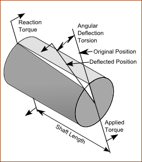
The Rigidity of rotary components is defined as the torque divided by the angular deflection:
Note:
|
|||||||||||
 Shaft with three different diameters, each of a different length. |
|||||||||||
The overall Rigidity of a shaft with three sections is:
This equation applies to components - gears, shafts, levers couplings - that you connect in series. The overall rigidity is always less than the rigidity of its least rigid component. The least rigid component has a very strong influence on the overall rigidity. Important: A very rigid component cannot make the overall rigidity any more rigid than the least rigid component. EXAMPLE: A Stepped Shaft
|
Gear Rigidity
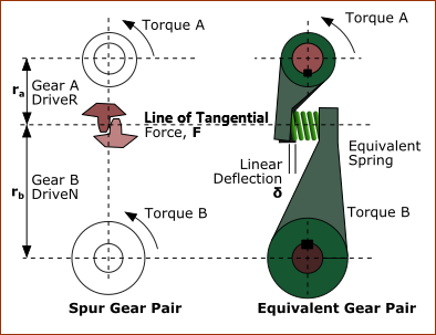
Industrial Machine use several type of gears - Spur Gears, Worm Gears, as well as Belt & Pulleys and Chain & Sprocket Drives. Generally, the pinion and wheel “disks” of a gear-pair have a torsional-rigidity that is high enough to be ignored. However, the gear-teeth themselves may deflect to contribute significantly to the overall elasticity of the transmission. Particularly when the diameter of the pinion and wheels is small, and/or the module of the gear-teeth are low. Both the driving and the driven teeth distort - they bend and they compress under Hertzian Stress. There is a linear-deflection that is tangential to the pitch-line of the gears. The load on each tooth varies somewhat as each tooth passes through the contact zone, and therefore the deflection also varies. But this variation is ignored here. The stiffness* of the the tooth can be defined as the tangential force divided by the tangential deflection when the contact point is on the common center-line, and can only be approximately calculated from the tooth dimension and material properties. When possible it is best to measure the torsional-rigidity rather than estimate it. However, we can derive some design guidance when we consider the relationship between tooth stiffness and torsional rigidity*. * In this topic: Stiffness relates to Linear Stiffness = Force / Linear Deflection - Rigidity relates to Angular Stiffness = Torque / Angular Deflection - |
|||||
|
|||||
The image shows a schematic of the rigidity of a “Spur Gear-Pair” that transmit a torque with a tangential force. The deflection of the gear-teeth are similar to those of a two levers whose tips we connect with a spring, as shown as the “Equivalent Gear-Pair”. Relating Force, Stiffness, and Linear Deflection Linear Force, , at the pitch-circle Linear-Stiffness, of gear teeth Linear Deflection,
Relating Torque, Rigidity, and Angular-Deflection Torques: and are the Torques () we apply to Gear and Gear , whose pitch circle radii are and , respectively. For small angles When Gear is rigid, the angular-deflection (radians) of Gear : When Gear is rigid, the angular deflection (radians) of Gear : Angular-Stiffness (Rigidity) of Gear relative to Gear is ( Torque ( ) / angular-deflection ( ) ) It is found with:
Similarly, the effective rigidity of Gear relative to Gear is
In general, Torsional-Rigidity (or Angular Stiffness), , is related to Linear-Stiffness, , acting at a Radius, , by the equation:
Torsional Rigidity of a gear is proportional to the Linear-stiffness, , of the gear tooth. Torsional Rigidity is proportional to the square of the Radius, . Top-Tip
As we have already seen, the overall elasticity () of a power transmission, is the sum of the elasticities of each section when connected in series (Equation 2). In effect, the elasticity of one section of the transmission is added to the next. When there is gearing between two sections, the transmitted elasticity is modified by the gear ratio. To study the effect of how we transmit elasticity with a gear-ratio, we assume a gear-pair with infinitely stiff teeth, the input gear has teeth, and the output gear has teeth. The gear ratio is: . (Note: a ratio that is usually less than one) Now, let: = Rigidity of all mechanical components before the input gear = Rigidity of all the mechanical components after the output gear also: = Input Torque of the Gear Pair = Output Torque of the Gear Pair Input Torsional (Angular) Deflection - twist, radians, of the input-shaft:
We can refer the Torsional Deflection at the Input-Shaft tp a Torsional Deflection at the Output-Shaft. Torsional Deflection of input-shaft transmitted (or referred) to the output-shaft:
That is, it is torsional-deflection of the input is less when observed from the output. Less when the output-shaft rotates slower than the input-shaft. The Output Torsional-Deflection of the output transmission-shaft, only, is:
We must add this to the Input Torsional Deflection that we have referred from the input-shaft. The Total Torsional-Deflection at the output end of the transmission is therefore:
The Total Elasticity ( ) as seen at the Output-Shaft is the Total Torsional Deflection divided by the Torque at the Output-Shaft.
If we ignore Gear Efficiency,
Therefore, the equation for overall elasticity at the output becomes:
This is similar to Equation 2, but the first term has been modified. The rigidity transmitted by gearing is proportional to the gear ratio squared. A reduction gear (output is slower than input) will increase rigidity. A step-up gear (output is faster than the input) will reduce rigidity. Note: Backlash transmitted by gearing is directly proportional to the gear ratio. TOP-TIP When a long transmission shaft is unavoidable and reduction gears are necessary, make the longest part of a geared transmission be the input high-speed shaft. It transmits less torque than the output low-speed shaft, and thus a smaller diameter based on strength, and its elasticity is reduced by the square of the gear ratio. |
Chains and Belts Rigidity
Equations 3, 4 and 5 can be applied to chain drives, but in that case the stiffness, , refers to the stiffness of the loaded length of chain between the chain-wheels. For a given chain size, the stiffness is inversely proportional to its length: very long chain drives should therefore be avoided as should small diameter sprockets. Belt drives behave in a similar way, but are generally less satisfactory than chain drives. Flat and Vee-belt drives are seldom used in cam system transmissions. Timing belt drives are common because they give an exact speed ratio for synchronizing with other mechanisms in the machine. Timing belts are made of reinforced synthetic rubber and are rather elastic compared to metal chains of similar strength. This is partly because the rubber belt teeth tend to roll slightly in the pulley grooves under heavy loads. More recently, the tooth profile has been improved so that this problem is reduced. Nevertheless, timing belt drives are very successfully used in cam transmissions because they are almost silent and need no lubrication. The backlash problem with chains and belts is similar to that with gears, but usually more severe. Slack chain drives are quite common in conventional steady torque transmissions, and not particularly detrimental to them. The use of chain tension-devices, of which there are many types commercially available, is strongly recommended for all cam transmissions, and are essential for high-speed or high-inertia applications. |
Shaft Bending - Bearing Support Rigidity
 Flexibility of Bearing Supports |
|||
One effect of using gears, chain drives, etc. in a transmission, which is often overlooked, is the flexibility of the bearing supports. The tooth load (action) produces an equal load (reaction) force at the gear supports. Note: When the gears are in a rigid casting (for example, a commercial gear-box and cam-box) the elastic deflections of the supports are usually small enough to be ignored. However, the reaction torque on the structure that supports the cam-box may itself be important. A rigid gear-box or cam-box is no advantage if it is not rigidly supported, or the frame deflects. Gears and chain wheels are sometimes unavoidably mounted on shafts far from the shaft bearings. This means the bending of the shaft due to the tooth load becomes a significant part of the overall rigidity of the transmission. Lateral deflection of the shaft has the same effect on angular displacement as tooth deflection and is mechanically in series with it. The image above shows how the linear deflection of the shaft produces an angular deflection of the gear (or chain wheel) so that the effect is similar to torsional elasticity. Here the shaft is displaced by the tooth contact force. The force is: , where is the tangential force and is the gear pressure angle. This acts at a distance of from the center of the shaft, Therefore, the shaft torque is: ... as expected. The angular deflection of the shaft, however, is
Thus, the effective Torsional Rigidity is: ... Equation 7 ... where is the lateral (sideways) deflection of the shaft. If the Lateral (Linear) Stiffness of the shaft in the plane of the gear is , then:
... and the equivalent Torsional Rigidity is...
This is the same as Equation 3. The relationship between lateral shaft stiffness and torsional rigidity is the same as tooth stiffness and is independent of the gear tooth pressure angle. Simple Support Shaft
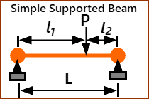
From beam bending theory, we find that for a simply supported shaft of constant cross-section, the lateral deflection at the sprocket for a load, , is:
... and its stiffness, N/m:
Where:
If the shaft bearings are themselves mounted on a flexible frame structure, the lateral deflection of the frame produced by bearing reaction forces must also be taken into account in a similar way to the lateral deflection of the shaft. Structural flexibility is in series with the transmission elasticity. |
|||
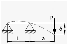
Overhung Shaft
From beam bending theory, we find that for a overhung shaft of constant cross-section, the lateral deflection for a load, , is:
... and its stiffness
Where:
|
Output Transmission
The estimation of rigidity of an Output transmission is exactly the same as for an input transmission. Most inputs, of course, drive rotary cams and therefore rigidity is expressed as the overall torsional rigidity. With output transmissions, however, we are dealing with a payload that is driven by the Follower. The Follower's motion may be linear (reciprocating) or rotary (oscillating or indexing). If the follower motion is a translating, linear motion, then the overall rigidity of the output transmission is expressed as a linear stiffness referred to the follower. If the follower motion is a swinging, rotating motion, then the overall rigidity of the output transmission is expressed as a torsional rigidity referred to the follower. Levers and Links
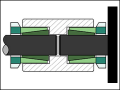
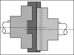
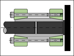
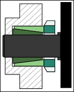
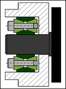
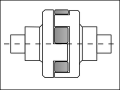
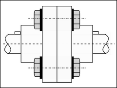
Couplings
|
|||||||||||