Reverse-Engineer Cams
Preamble:
What does “To Reverse-Engineer a Cam” mean?
The simplest definition is to manufacture a cam that is the same as the original cam.
You can copy-mill a cam. For this you need a “master-cam” in good condition. If you copy-mill a worn cam, the original motion is not transferred to the new machine, of course.
However, OEMs (Original Equipment Manufacturers) want to continuously improve the performance of their machines.
One way to improve machine performance is to improve the follower's motion provided by the cam. The process we describe below includes MechDesigner and MotionDesigner to improve the performance of a machine.
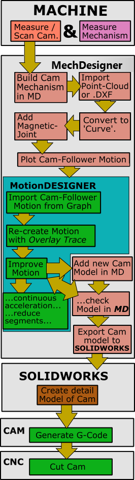
Process to improve the performance of a Machine:
|
C.M.MCam Measurement Note: Before you measure the cam-profile, inspect its surface to see if it is worn. Measure the cam-profile. Measure the bore of the cam-plate to locate the rotating-axis of the cam-shaft. Measure the position of a key-way or a dowel-hole that is the timing-angle of the cam-profile on the cam-shaft. Make a drawing of the Cam to indicate the key-features - e.g. The cam's minimum and maximum radius, and where is it worn. Measurement of the Cam and Follower's Kinematic-Chains If the Follower-Part oscillates and the Follower-Profile is a Roller bearing, measure: •the distance between the rotational centers of the Cam and the Follower. •the distance between the center of the Roller bearing and the rotational center of the Follower. •the diameter of the Roller, or get its part-number •the minimum and maximum radius of the cam If the Follower-Part reciprocates, measure: •the offset distance between the sliding-axis of the Follower-Part and cam's rotational center •the offset between the Roller bearing and the sliding-axis of the Follower-Part •the diameter of the Roller bearing, or get its part-number •the minimum and maximum radius of the cam Other parts in the kinematic-chains: Measure the distance between each fixed axis, the position of slide axes, and the length of each part in the Follower's kinematic-chain. MechDesigner1.Model the kinematic-chains for the Cam and the Follower kinematic-chains. 2.Import the Cam-Profile To do this: a.Import a Point-Cloud : Add a Point-Cloud FB to the rotating Cam-Part; edit the Point-Cloud dialog to import data you have measured for the cam-profile. Use the Point-Cloud dialog to fit a Curve to the Point-Cloud data. or a.Import a DXF-Drawing of the Cam; edit a CAD-Line to show the DXF-Drawing of the cam. Convert DXF Entities to MD sketch-elements. Make a sketch-loop to represent the cam. Add a Profile element to the sketch-loop that represents the cam. or a.Import a sketch from SOLIDWORKS: to import a SOLIDWORKS sketch of the cam. Make sure the imported sketch is a sketch-loop. Use Merge-Point, if needed. Add a Profile element to the sketch-loop. 3.Add a Magnetic-Joint FB to pull the Follower-Profile onto the Curve (derived from the Point-Cloud) or the Profile element (derived from the DXF or SOLIDWORKS sketch), to drive a Motion-Dimension FB. 4.Connect wires from the Motion-Dimension FB that is driven by the Magnetic-Joint to a Graph FB to plot the Follower's motion - its displacement, velocity, and acceleration. MotionDesigner1.Use the Data Transfer Table to import the plot / data from the Graph FB 2.Put the Data in the table to a Z-Raw-Data or Position-List motion-law (List segment type) (this is to make sure you do not lose the data if you close MechDesigner). 3.If necessary, 'Get the motion' from the Z-Raw-Data (if the Data Transfer table is empty after closing MechDesigner). 4.Add a new Motion and Motion tab and 'Put the data' as an 'Overlay Trace'. 5.Edit the new motion so that it becomes almost the same as the 'Overlay Trace'. MotionDesigner - MechDesigner Interaction1.Build a new model with new kinematic-chains to represent the Cam and Follower again. 2.Put the Joints and Parts in the same positions as those in the original kinematic-chain. 3.Add the new motion, which is similar to the Overlay-Trace. Now there are two motions to compare - one driven by the Magnetic-Joint and the other by the new motion. Improve the New Motion 1.Make sure the acceleration of the new motion is continuous 2.Reduce the number-of-segments 3.Balance the new motion to reduce peak accelerations and velocities 4.Change motion-laws to suit the application 5.Check the Pressure-Angle and Radius-of-Curvature to make sure they are acceptable. Export the Cam to SOLIDWORKS •Use a Cam-Data FB and Cam-Coordinates dialog to export the Cam directly to SOLIDWORKS save as a STEP file, a TEXT file of the XY Coordinates, a SLDCRV file to import as a Curve feature in SOLIDWORKS, or a DXF file to import into any CAD. SOLIDWORKS•If necessary, in SolidWorks, move the cam to put it in the correct orientation for machining. •Add various details - bore, boss, key-way, , dowel holes. ... to make a full cam model •From the model, add a drawing with tolerances •Export to C.A.M. C.A.M.•Generate the G-Code that you need for a C.N.C. Machine. •If necessary, reverse the cam surface data to cut the cam with 'climb' or 'conventional' milling. C.N.C.•Machine the Cam. |