Compare Piggyback Sliders and Blend-Curve
We will use two ways to design a path that moves up and over an obstacle.
•Piggyback Sliders in the X-axis and Y-axis direction
•Sketch-Path and Motion-Path FB
Piggyback Sliders
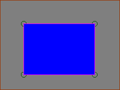 |
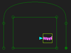
STEP 1: Add an Obstacle to the Base-Part To see the obstacle, we will add a rectangle.
|
|||
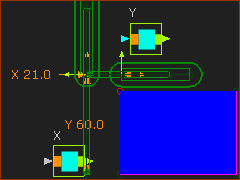 |
STEP 2: Add Piggyback Sliders
|
|||
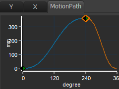
 X,Y plot values for each Blend-Point |
STEP 3: Design Motions for the X-axis Slider.
|
|||
 X,Y plot values for each Blend-Point |
STEP 4: Design Motions for the Y-axis Slider.
|
|||
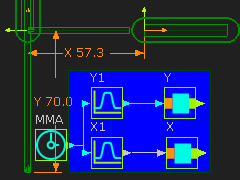 |
STEP 5: Add Function-Blocks
|
|||
|
STEP 6: Add a Trace-Point to see the Path
<<< click to play video
|
|||
 Point Properties dialog |
STEP 7: Open the Point Properties dialog
The Point Properties dialog is now open.
STEP 8: Select the Vectors to show
Magnitude = √(X2 + Y2)
STEP 9: Cycle the model
|
|||
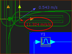 |
The Maximum Vertical and Horizontal velocity and acceleration vectors are equal to those of the X and Y Velocity and Acceleration graphs in MotionDesigner. You can find the maximum acceleration with these methods: •Move the MMA until the Acceleration Vector is a maximum value - see left •Use a Point-Data FB with a Graph FB to measure and plot the motion-values •Use a Stats FB to review the data values - e.g. Min, Max, RMS. |
Slow Place motion, Fast Return Motion
|
We will imagine that the motion is to guide a Pick and Place Robot. We may want the Robot to move more rapidly in the Pick direction ( right-to-left) as compared with the Place direction ( left-to-right) STEP 10: Edit the Motions to Return more quickly.
You will find it is difficult. Especially, if you want the shape of the Pick and Place paths to be the same. Small changes to the X or Y motion can give large changes to the shape of the overall Path. It takes a while to create any suitable motion with Piggyback Sliders. There is a different approach - or an Alternative Strategy. |

Alternative Strategy for “Fast Pick” and “Slow Place” motion.
 Motion to modify the MMA |
|
|
 Output of Motion FB is input to Motion FB |
||
|
Motion-Path FB.
|
STEP 1: Add an Obstacle
|
||
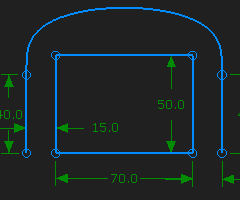 |
STEP 2: Add a sketch in the Base-Part to give the XY-Path
|
||
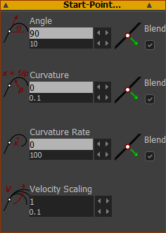 |
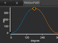
STEP 3: Look in the Blend-Curve dialog
The image is the Start-Point separator, only |
||
 |
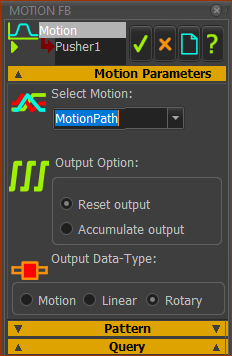
STEP 4: Add a Motion-Path FB to the sketch of the XY-Path.
The Motion-Path FB is in the graphics-area. The Motion-Point |
||
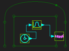 |
STEP 5: Add a Motion FB and Linear-Motion FB
The Motion-Point |
||
 |
STEP 6: Edit the Motion that is linked to the Motion FB There are two ways to make sure the Motion-Point moves along all of the XY-Path, and returns. Method A
|
||
 |
Method B
TOP-TIP:
|
||
 |
STEP 7: Edit the Motion so the first segment is longer than the second segment.
|