Summary
The kinematic-chains for the Cam-Part and the Follower-Part are simple:
•The Cam-Part is a Rocker that rotates with a constant angular-velocity - a Cam-Shaft
•The Follower-Part is a Slider that reciprocates back and forth - the term we use is Translating Follower.
The term for the shape of the Follower-Profile is Flat-Faced Follower.
|
Add the Parts Cam and Follower Parts.
 Sliding-Axis anda Line to locate the start-Point
 Dimensions to locate the position and direction of the Sliding-Axis |
STEP 1: Add a new Mechanism-Editor to the Front-Plane

|
1.
2.Model-Editor: |
|
3.Model-Editor: Click the Front Plane
4.Click  in the Command-Manager. in the Command-Manager. |
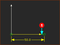
STEP 2: Edit the Base-Part to add a Line for the Rotational center of the Cam-Shaft
1.Edit the Base-Part
2.Part-Editor: . Drag to add the Line. Its start-Point locates the center of the Cam-Shaft locates the center of the Cam-Shaft
3.Part-Editor: Click the Line
4.Part-Editor: Click the Y-axis then the start-Point of the Line, then again,
5.Part-Editor: Click the X-axis and the start-Point of the Line
6.Part-Editor: : Enter 50mm |
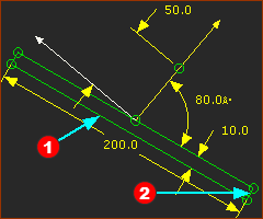
STEP 3: continue .... add a Line for the Sliding-Axis of the Translating Follower
|
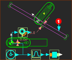
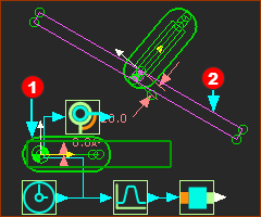
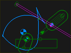
In the images below, you can see that the sliding-axis of the Follower-Part is not vertical or horizontal. It is also offset from a radial axis from the rotating-axis of the Cam-Shaft . is not vertical or horizontal. It is also offset from a radial axis from the rotating-axis of the Cam-Shaft .
The offset will not change the cam. However, it moves the contact point between the Cam-Profile and the Follower-Profile to the left or the right of the sliding axis. Thus, it will change the overturning moment, which is the moment that tries to bend the sliding-Part in its slide-way.
|
|
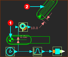
STEP 4: Add the Cam as a Cam-Shaft.
1.: Click and drag to add the Part
2. Click the start-Point of the new Part and the start-Point of the Horizontal Line in the Base-Part. Click the start-Point of the new Part and the start-Point of the Horizontal Line in the Base-Part.
3.: Click the Pin-Joint, click the Horizontal Line in the Base-Part, and click the CAD-Line in the new Part.
4.Click the FB in the toolbar and then the graphics-area.
5.Connect a wire from the Linear-Motion-FB to the Motion-Dimension FB.
6.Edit the Motion-Dimension FB> Base-Value = 0 |
|
STEP 5: Add the Follower-Part
1.: Click and drag to add the Part
2. Click the CAD-Line along the new Part and the Line in the Base-Part, . The Slide-Joint is the sliding-axis of the Follower-Part
3.: Click the Slide-Joint, click the start-Point of the Line and sliding-axis of the Base-Part, and the start-Point of the Follower-Part
4.Click the FB in the toolbar and then the graphics-area.
5.Click the FB in the toolbar and then the graphics-area.
6.Connect wires from the Linear-Motion-FB to the Motion FB and also from the Motion FB to the Motion-Dimension FB. |
|
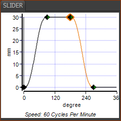
A Motion
|
See MotionDesigner Help. Use the Blend-Point Editor to edit the motion.
Blend-Point
No
|
X - Input
Cam-Shaft
|
Y - Output
Follower
|
1
|
0
|
0
|
2
|
90
|
30
|
3
|
180
|
30
|
4
|
280
|
0
|
1
|
360 / 0
|
0
|
|
Add the sketch-loop to the Slider for the Follower-Profile
When the sketch-loop and Profile in contact with the cam is a Circle, we call it a Follower-Roller. When the Profile in contact with the cam is from a Line, we call it a Flat-Faced Follower.
In all cases, the shape of the Follower-Profile must be a . For a Flat-Faced Follower, one of the sketch-elements is a Line.
|
STEP 1: Add the shape of the Flat-Faced Follower to the Follower-Part
1.Edit the Part that is the Follower - a Slider
2.Part-Editor: Add a Line that will be in contact with the Cam.
•Add Line with its mid-point at the start-Point of the Slider. You may need to edit the length of line later.
•Line is at an angle relative to the Slide-Joint. In this case it at 80º.
3.Part-Editor: Add three more lines to complete a long, narrow rectangle, with, perpendicular (⊥) sides . The rectangle must be a .
4.Exit the Part-Editor |
|
|
STEP 2: Add a Profile to the sketch-loop of the Flat-Faced-Follower.
To add the Profile, do:
1.Click
2.Click the long rectangular . sketch-loop.
3.Click  in the Command-Manager. in the Command-Manager. |
|
Add the 2D-Cam
When you add the 2D-Cam, we always calculate for you the Inner (Internal) and Outer (External) Cams. For a Flat-Faced Follower, we usually hide the Outer cam.
|
STEP 1: Add a 2D-Cam
1.
2.Mechanism-Editor: Click the Part-Outline of the Cam-Shaft
3.Mechanism-Editor: Click the Profile - the long, narrow rectangle.
4.Click in the Command-Manager
or
4.Right-click the graphics-area |
|
|
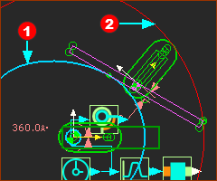
In the image, there are two Cam-Profiles: and .
The Cam-Profiles are the Inner and the Outer
The Inner Cam-Profile contacts the long-side of the Follower-Profile.
The Outer Cam-Profile contacts one corner of the Follower-Profile.
|
|
STEP 2: Hide the Outer Cam-Profile
1.Double-click the 2D-Cam to open the 2D-Cam dialog
2.In the 2D-Cam dialog > Display tab > Cam-Profile Display
3.Enable |
|
|
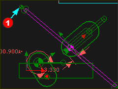
Trouble-shooting 1
Does the Cam fail to build?
If you do not see the 2D-Cam, it is possible that the Flat-Faced Follower is not wide enough. The contact-point moves past one end of the Follower-Profile. See image . You must do something!
Do one or more of:
a)Improve the Motion-Design - Can you improve the motion of the Follower - Recommended.
b)Edit the sketch of the Flat-Face Follower so that he Follower-Profile is wider - I recommend you use a Design-Set.
c)Move the sliding-axis nearer to the axis of the Cam-Shaft - see b) Design-Set.
d)Move the Flat-faced follower (rectangle) to one side of the Slider - see b) Design-Set |
Trouble-shooting 2
Does the Cam-Profile have a fish-tail?
If the Cam-Profile has a fish-tail, you must usually edit the motion, to reduce the peak velocity and/or the peak acceleration of the Follower.
•Reduce the displacement of the Follower / Slider, and/or
•Increase the period (Segment-Width) of the segment that coincides with the contact of the fish-tail with the Flat-Faced-Follower. |
|
|