6A2.2: Swinging-Offset Flat-Faced Follower

<< Click to Display Table of Contents >>

Navigation:  Getting Started Tutorials - MechDesigner > Tutorial 6: Cams: Flat, Barrel, Globoidal, 'Slot' > 6A2: Cam-Shaft & Flat-Faced Follower >

6A2.2: Swinging-Offset Flat-Faced Follower

Summary

In this tutorial, the Flat-Faced Follower is Swinging and Oscillating.

The kinematic-chains for the Cam-Part and the Follower-Part are simple:

The Cam-Part is a Rocker that rotates with a constant angular-velocity - a Cam-Shaft

The Follower-Part is a Rocker that oscillates back and forth - the term we use is Swinging or Rotating Follower.

The term for the shape of the Follower-Profile is Flat-Faced Follower.

Add the Parts for the Cam and the Follower

GST-6A2-201

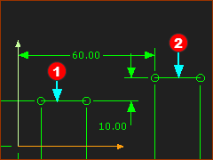
STEP 1: Add a Mechanism-Editor

STEP 2: Add Lines to the Base-Part

1.Edit the Base-Part

2.Add LineRed-14-1 - its start-Point is the center of the Cam-Shaft

3.Add LineRed-14-2 - its start-Point is the center of the Swinging-Follower

4.Add dimensions and constraints to the Lines

5.Exit the Part-Editor

GST-6A2-202

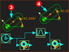
STEP 3: Add the Cam-ShaftRed-14-3

1.Add Part Red-14-3

2.Add a Pin-Joint

3.Add a Motion-Dimension FB

4.Add a Linear-Motion FB

5.Connect a wire from the Linear-Motion FB to the Motion-Dimension FB.

The Cam-Shaft rotates one time per machine-cycle.

STEP 4: Add the Swinging-FollowerRed-14-4

1.Add Part Red-14-4

2.Add a Pin-Joint

3.Add a Motion-Dimension FB

4.Add a Motion FB

5.Connect a wire from the Linear-Motion FB to the Motion FB, and from the Motion FB to the Motion-Dimension FB.

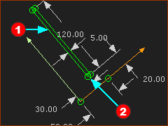
Add the Flat-faced Follower

The Flat-Faced Follower must be a sketch-loop. One of the sketch-elements must be a Line.

The best shape for a Flat-Faced Follower is a long, narrow rectangle. One of the long sides of the rectangle becomes the contact face.

GST-6A2-203a

STEP 1: Add the Flat-Follower Follower sketch-loop

See dimensions in the image to the left.

1.Edit of the Swinging-Follower Part.

2.Add LineRed-14-1b - the long side of the rectangle

3.Add Lines to add a rectangle : LineRed-14-2 is short relative to LineRed-14-1b . LineRed-14-1b and LineRed-14-2 are perpendicular (⊥).

4.Add dimensions and constraints.

5.Exit the Part-Editor (e.g. Double-click a sketch-element)

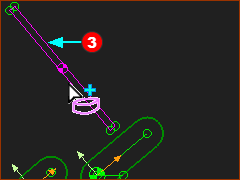
STEP 2: Add a Profile/Extrusion to the sketch-loop

1.Click Solids toolbar > Add Profile

2.Click the sketch-loopRed-14-3

3.Click OK-tiny-11-15 in the Command-Manager

In this case the flat-face follower is offset from the Pin-Joint.

GST-6A2-204

Define a Motion

GST-6A2-205

STEP 1: 
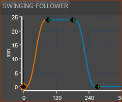
Define a Motion

See MotionDesigner Help. Use the Blend-Point Editor to edit the motion.

Blend-Point

No

X - Input

Cam-Shaft

Y - Output

Follower

1

0

0

2

90

24

3

180

24

4

280

0

1

360 / 0

0

Add the 2D-Cam

Cam is Undercutting

Cam is Undercutting

New Motion Timing

New Motion Timing

Final Cam

Final Cam

STEP 1: Add a 2D-Cam

1.Click Machine elements  toolbar > Add 2D-Cam

The Command-Manager has two selection boxes for two elements:

2.Click the Part-Outline of the Cam-Shaft Part Red-14-1b

3.Click the Flat-Faced Follower Profile Red-14-2

4.Click OK-tiny-11-15 in the Command-Manager.

With a Flat-Faced Follower, the Outer Cam-Profile is not usually useful.

STEP 2: Hide the Outer Cam-Profile

1.Double-click the Cam-Profile to open the 2D-Cam dialog.

In the 2D-Cam dialog > Display tab > Cam-Profile Display

2.Enable Inner.

The image above indicates that cam undercuts - see the fish-tailRed-14-3.

STEP 3: Edit the Motion

Use the Blend-Point Editor to edit the timing of the motion - the X-axis of the Blend-Point.

Blend-Point

No

X - Input

Cam-Shaft

Y - Output

Follower

1

0

0

2

140

24

3

180

24

4

280

0

1

360 / 0

0

Now, the Cam does not undercut.