A Typical Mechanism in a Packaging Machine- B

Typical Mechanism
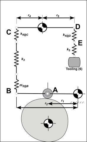
This is a typical mechanism that you will find in packaging, textile, and assembly machines.
We want to find the lowest natural frequency as it determines the overall performance.
To find its lowest natural-frequency, we treat the mechanism as a lumped-parameter model. We calculate the mass, mass moment-of-inertia, and spring-rate (stiffness) of each part. Then we refer these to one place in the mechanisms. We can them analyze the whole mechanism with a single degree-of-freedom model with one mass and one spring.
In this example, we refer the masses and spring-rates to the Follower-Roller.
All parts are Steel, .
STEP 1- Lump the masses of the links to different points
Find the Mass and Effective Mass of each element.
 Lumped Masses Only Model
|
Tooling, 6 mass is .
Short Push-Rod, (5) The mass of the is found from CAD.
Lever, 4 rotates about Radius: Mass Moment of Inertia of about pivot : from CAD: Refer the inertia of the , as a mass at point
Long Push-Rod, 3 The mass of the is found from CAD.
Follower, 2 rotates about Radius: . Mass Moment of Inertia of about pivot is found from CAD: Refer the inertia of the as a mass at point
Follower-Roller, 1 The mass is found from the catalog information.
|
STEP 2 - Refer the Lumped-Masses to the Follower-Roller at A
Short Push-Rod (5) + Tooling (6) Add the mass of the and the
Refer the mass at to Use the square of the ratio of the radii : ,
Add the Effective Mass of Lever (4)
Add the mass of the Long Push-Rod Add the mass at to the mass of the , , to point .
Add the Effective Mass of the Follower
Refer to the Follower-Roller Refer the Mass at to the at , and add the Mass of the Follower-Roller.
This is the effective mass to be used in the 1-DOF model of the system. |
STEP 3 - Lump the Springs
Find the Effective Spring Constant of each element.
|
Tooling, 6 Assume to be infinitely stiff. Short Push Rod, 5 The Short Push-Rod is a steel tube with OD of 25mm and ID of 18mm (Area ). The length is
Left-side of the Lever 4, at D The stiffness was found from CAD by fixing the left-side of at , and applying a vertical load of to
Right-side of the Lever 4, at C The stiffness was found from CAD by fixing the right-side of , and applying a vertical load of to
Push-Rod, 3 The Push-Rod is a steel tube with OD of 25mm and ID of 18mm (Area ). The length is
Follower, 2 A simple supported, overhung beam. To analyze its stiffness in CAD: add a support at , add at , and apply a load of at vertically.
|
STEP 4 - Refer the Springs Rates to the Follower-Roller.
Combine spring-rates k5, and k4@D Springs in Series We use the Spring in Series equation to combine these Spring-Rates.
Move k5 to C Bring the 'spring' at the right-hand of , , to point
Combine spring-rates k2, k3, k4, and k5@C at B Springs in Series We use the Spring in Series equation to combine these Spring-Rates.
Refer Spring-Rates at B to A Use the ratio of two radii.
This is the Effective Spring-Rate to be used in the one degree of freedom model. |
Calculate the Natural Frequency
|