Geared Four-Bar Mechanisms
Geared Four-bar Mechanisms are usually assembled with:
•A four-bar mechanism, in which one Part rotates continuously.
•One or two Gear-Pairs
•The input gear is fixed to the Coupler, at the distal end of the Crank or the Rocker
•The output gear is usually at the joint with the Base-Part of the respective Crank or the Rocker
Geared Four-Bar Mechanisms are often used as Function-Generators.
Geared Four-bar Mechanism Configurations
One Gear-Pair
Regressive and Ir-regressive Gears. (I do not know why they are called regressive and ir-regressive gears).
•Regressive gears - a gear at each end of the Crank of a four-bar.
•Ir-regressive gears - a gear at each end of the Rocker of a four-bar.
Note: Four-bar is a common term for a kinematic-chain with four Parts - usually with four Pin-Joints, usually one Part is the Base-Part.
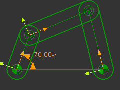
Regressive Geared Four-bar
|
STEP 1: A Four-bar Line-of-Centers
|
||
|
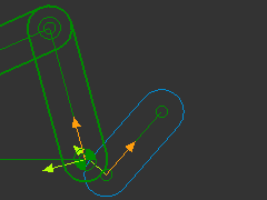
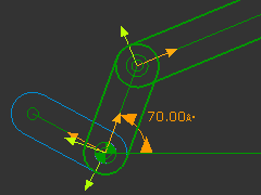
STEP 2: Add the rotating-Part for the output of the Regressive Gear-Pair
There are two Points at the origin of the Crank - the start-Point of the Crank, and the start-Point of the Line in the Base-Part. |
||
|
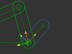
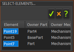
The Select-Elements dialog opens because you have clicked three Points in total STEP 2: Select two Points in the Select-Elements dialog
Why select the start-Point of the Crank? The Line-of-Center is the CAD-Line in the Crank. The Pin-Joints be with Points at each end of the Line-of-Center. |
||
|
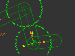
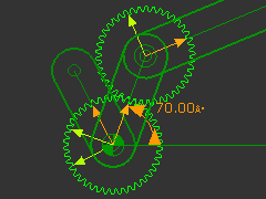
STEP 4: Add the Regressive Gear-Pair
|
||
|
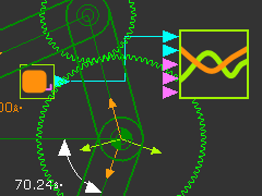
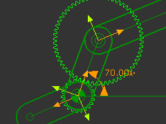
STEP 5: Edit the Gear-Pair
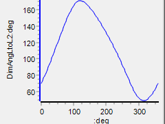
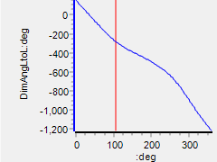
STEP 6: Plot a Graph of the Output vs the Rotation of the Crank
|
||
|
|||
|
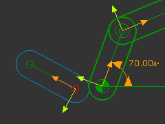
Ir-regressive Geared Four-bar
|
STEP 1: A Four-bar Line-of-Centers
|
|
|
STEP 2: Add the rotating-Part for the output of the IR-Regressive Gear-Pair
There are two Points at the origin of the Rocker - the start-Point of the Rocker, and the end-Point of the Line in the Base-Part. |
|
|
The Select-Elements dialog opens because you have clicked three Points in total STEP 3: Select two Points in the Select-Elements dialog
Why select the start-Point of the Rocker? The Line-of-Center is the CAD-Line in the Rocker. The Pin-Joints be with Points at each end of the Line-of-Center. |
|
|
STEP 4: Add the Regressive Gear-Pair
|
|
|
STEP 5: Edit the Gear-Pair
|
|
|
STEP 6: Plot a Graph of the Output vs the Rotation of the Crank
|
|
|