Mathew Boulton And James Watt Steam Engine
Mathew Boulton, 1728-1809, financed and worked with James Watt, 1736-1819, to improve Steam Engines. They entered a partnership in1775. The design below uses a gear-pair to rotate a flywheel at twice the speed of the crank. Why was this useful? It made him a lot of money. When the flywheel rotates at twice the angular velocity, a smaller flywheel can store the same amount of energy. The energy in the flywheel keeps the engine turning as the crank moves though the bottom and top dead centers. A smaller flywheel is useful when you need to install the Steam Engine in a small spaces - such as a coalmine. On a train, you might get the engine closer to the ground to make it more stable. A different innovation by Watt was his straight-line mechanism. (This is in Tutorial 10.4). He added a pantograph mechanism to amplify the straight-line motion, and so reduce the size of the engine for a given stroke of a piston. I show this in the video. |
||||
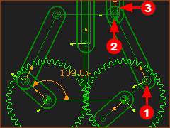
This example is a from the Boulton and Watt Steam-Engine. •The Part that is kinematically-defined is the Connecting-Rod of the Crank-Slider mechanism. •The Line-of-Centers is the CAD-Line on the Crank. •The Driven-Gear is on a Part with its axis at the center of the Crank •The flywheel is attached to the Driven-Gear at the center of the Crank. |
||||
|
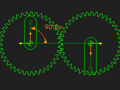
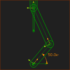
STEP 1: Add a Crank - Slider Mechanism
Before this Patent, the Flywheel was joined to the original Crank. In the Patent, the Flywheel is a rotating- Part that has the same center as the original Crank. STEP 2: Add a Part
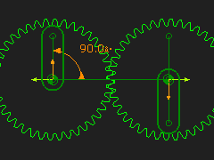
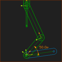
STEP 3: Add a Pin-Joint
|
|||
|
||||
|
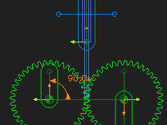
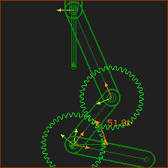
STEP 4: Add a Gear-Pair
STEP 5: Cycle the model
|
|||

Straight Line Mechanism for Engines 1: Cartwright's Geared Engine
|
STEP 1: Add a Simple Gear-Pair - Option 1
|
|
|
STEP 2: Edit Gear 2 to add a Line
|
|
|
STEP 5: Add a vertical Line in the Base-Part STEP 6: Constrain it to the Midpoint of the Line-of-centers STEP 7: Add a Part and Slide-Joint STEP 8: Add a Line so it is Horizontal It is best to add the Line |
|
|
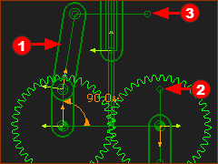
STEP 9: Add a Part We would want to add a Part that mirrors Part We must add two Parts. That is, a dyad. THIS IS NOT A CHEAT - IT IS A KINEMATIC REQUIREMENT. In reality, because the two sides of the mechanism cannot be an exact mirror, there must be enough backlash to accommodate the differences. In Kinematics, Pin-Joints do not have backlash. |
|
|
STEP 10: Add a dyad I have chosen to add an R-R-P dyad. - I could also add an R-R-R dyad, with one short Part at the Point 2 or Point 3 In the image, the Joints are: R = R = P = The kinematic-chain can now cycle. The Slider in the new R-R-P does not move, but it is still needed to make the kinematic-chain. |