Geared Five-Bar Mechanisms
Geared Five-bar mechanisms are usually built with:
•One Gear-Pair
+
•One dyad
Applications
Geared five-bar mechanisms are interesting... to some people. They can give:
•Complex Coupler Curves
•Complex Function Generators
Geared Five-bar Mechanism Configurations
There are four ways you can edit a Geared Five-bar Mechanisms:
1.Gear-Pair: use fixed or orbiting gear centers
2.Dyad: use one of the five dyads: R-R-R, R-R-P, R-P-R, R-P-P, or P-R-P.
3.Gear Mesh: use an external or internal gear-mesh
4.Basic Design: edit the number of teeth on each gear
Typical Geared Five-bar Mechanism Configurations
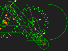
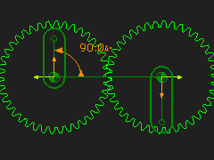
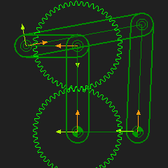
Complex Coupler Curves (Fixed Gear-Pair and R-R-R Dyad)
|
Gear-Pair: 1:1, Fixed-centers, External Mesh Dyad: R-R-R dyad Application: Coupler Curve A Gear-Pair has 3 Parts: •Base-Part, Input Crank, and Geared-Rocker A Dyad has two Parts. Typically, the dyad is an R-R-R dyad. STEP 1: Add a Simple Gear-Pair - Option 1 |
|
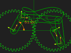
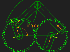
STEP 2: Add an R-R-R dyad To remind you: 2.a. Add two Parts 2.b. Add three Joints STEP 3: Edit the Part used for Gear 2 Add a Line that radiates from the center of the Geared-Rocker - the Driven-Gear. Add dimensions for the length and angle of the Line. Use the end-Point of the Line for one of the Pin-Joints in the R-R-R dyad. You can edit the angle of the Line to edit the phase of the Geared Rocker relative to Driving-Gear. The design parameter options are: 1.Gear Ratio between Gear 1 and 2 (Number-of-Teeth); 2.Phase between the Gears; 3.Length of Driving-Gear and Driven-Gear Parts. 4.Length of each Part in the dyad. |
|
STEP 4: Change the number-of-teeth with the Gear-Pair dialog - for example 60:40. In this case, it takes two rotations of the input crank to complete the function at the output shaft To plot the complete Trace-Point, you must rotate the input crank two times faster. STEP 5: Add a Gearing FB; Gearing-Ratio = 2 STEP 6: Connect the wires between the Linear-Motion FB, Gearing FB and Motion-Dimension FB STEP 7: Connect the Output from the Motion-Dimension FB to the X input of the Graph FB |
|
Here is an 'interesting' Coupler Curve.
In these Coupler Curves we are plotting the motion of the middle joint of the R-R-R dyad. You can add a Point to one of the Parts to give even more complex Coupler Curves. |

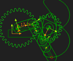
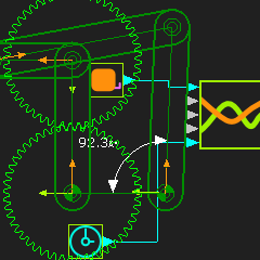
Complex Function Generators (Orbiting Gear-Pair and R-R-R Dyad)
|
Gear-Pair: 1:1, Orbiting-centers, External Mesh Dyad: R-R-R dyad Application: Function-Generation Typically, you can get interesting motions from a Geared Five-bar that has a Gear-Pair with an Orbiting center. It is called a Function-Generator. STEP 1: Add an Epicyclic Gear-Pair STEP 2: Make the gear ratio 1:1 (for example 50:50 Gear Teeth) |
|
STEP 3: Add an R-R-R dyad between the end the Geared Rocker and the Line in the Base-Part
|
|
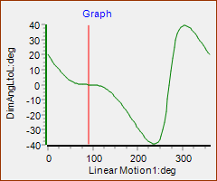
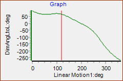
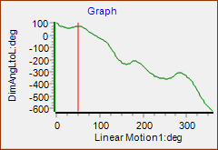
STEP 4: Measure the angular position of the output Part over a Machine Cycle with a Measurement FB STEP 5: Add a Graph FB STEP 6: Connect the Measurement FB to an input of the Graph FB Add a Design-Set to give a quick way to edit the Part lengths. This Graph is of the Output Shaft Rotation as a Function of the Input, Constant Speed, Shaft Rotation. Notes about Mechanism Synthesis It is typical that an output vs input relationship is given. Then a mechanism is found to provide the function. Four-bar mechanism Function-Generators are limited. For example, it is not easy to synthesize a mechanism that oscillates the output shaft more than one time in a machine cycle. It is clear from this graph that more complex functions are possible. |
|
|
|
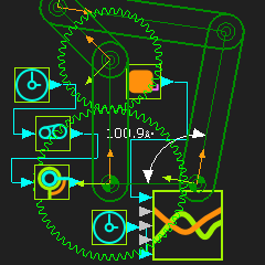
Change the Gear Ratio to give more interesting Function Generation You can change the gear ratio of the Gear-Pair to give more complex function generation. STEP 7: Change the Gear ratio - for example 60:40. In this case, it takes two rotations of the input crank to complete the function at the output shaft STEP 8: Add a Gearing FB; make the Gear ratio 2 STEP 9: Connect the wire between the Linear-Motion FB, Gearing FB and the Motion-Dimension FB STEP 10: Connect the Output from the Motion-Dimension FB to the X input of the Graph FB |
|
The Y-axis in the Graph is for two rotations of the crank to give the complete Function-Generation for the 60:40 gearing ratio. |
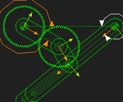
Geared Five-Bars: (Gear-Pair and R-P-R Dyad)
|
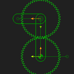
Gear-Pair: 1:1, Fixed-centers, Internal Mesh Dyad: R-P-R Dyad Application: Coupler Curve
|
|
Gear-Pair, 2:1 Fixed-centers with an R-P-R dyad Application: Coupler Curve •The Gear-Pair ratio changed to 60:40 •The Crank must rotate tow times to complete the Trace-Path •To plot the complete Coupler Curve you should add a Gearing FB before the Motion-Dimension FB and make the Gearing Ratio = 2. |
|
Gear-Pair 1:1, Fixed-centers, R-R-P dyad. Application: Coupler Curve
|
|
Gear-Pair 1: 1, Orbiting-center, R-P-R dyad Application: Function-Generation |
|
The motion of the output Rocker as a function of the input-rocker. It has a reasonable dwell.
|