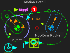
Fixed Pulley Centers - a Belt driven by a Driving-Pulley
This design arrangement has one Driving-Pulley, one Driven-Pulley, and one sketch-path to represent the Belt.
A Driving-Pulley drives the Belt and also a Driven-Pulley.
Notes:
The sketch-path that represents the Belt can be an open or closed sketch-path. Typically, it is a closed sketch-path.
You can control the length of the belt with a - see Control the Length of the Belt
Preparation: Sketch-Path and Pulley Parts
|
|
STEP 1: Add a closed sketch-path to represent the path of the belt.
1.Edit the Base-Part :
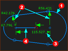
Add a sketch-path to represent the path of a Belt . In this example, the sketch-path has two Arcs and two Lines. . In this example, the sketch-path has two Arcs and two Lines.
Click : Click each Arc  . The radius of each Arc is not important. . The radius of each Arc is not important.
Click Click the center-Points of the Arcs . The distance between the Arcs is not important . The distance between the Arcs is not important
2.Exit the Part-Editor |
STEP 2: Add a Line to the sketch
1.Edit the Base-Part
Click - drag in the graphics-area to add the Line . .
Click : Click the start-Point of the Line and the center-point of an Arc.
Click : Click the Line
Click : Click the Line
2.Exit the Part-Editor |
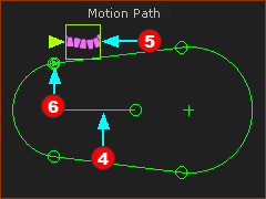
STEP 3: Add a Motion-Path FB
1.
Click one of the sketch-elements in the sketch-path that represents the belt.
Click  in the Command-Manager in the Command-Manager
|
A Motion-Point is at the start-Point of the sketch-element that you select. is at the start-Point of the sketch-element that you select.
The Motion-Point is difficult to see because it is coincident with the start-Point.
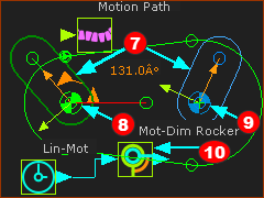
STEP 4: Add the Parts for the Pulley's
One rotating-Part is kinematically-defined (it is a Rocker), the other rotating-Part is not kinematically-defined.
|
 Add Motion-Path FB - Command-Manager |
|
|
|
|
Use Add Pulley
|
|
STEP 1: Add the Driving-Pulley

|
1. |
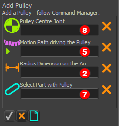
Add Pulley opens in the Command-Manager.
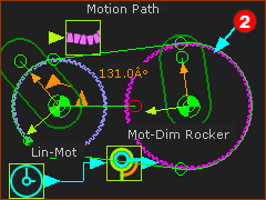
You must select four elements - see the elements   in the images above in the images above
1.Click Pin-Joint
2.Click Motion-Path FB
The Part-Editor opens to show the sketch-path of the Belt in the Base-Part
3.Click the radius Dimension of the Arc sketch-element at the Pin-Joint
The Part-Editor closes.
4.Click the Part that has the Pin-Joint
5.Click  to close the Command-Manager. to close the Command-Manager. |
We add for you a Driving-Pulley
Notes
The Part that is kinematically-driven (a Rocker, in this case) is the Driving-Pulley.
Belt Speed = Radius of Driving-Pulley × Angular-Velocity of the Driving-Pulley
|
|
|
|
|
|
STEP 2: Add the Driven-Pulley
Do Step 1 again but select the other Pin-Joint , and the Part that is not kinematically-defined. , and the Part that is not kinematically-defined.
|
We add for you a Driven-Pulley
The default colors of a Driven-Pulley and a Driving-Pulley are different.
|
|
|
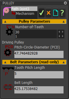
STEP 3: Edit the Driving Pulley
1.Double-click a Pulley
The Pulley dialog is now open
2.Edit the Number-of-Teeth
3.Close the Pulley dialog |
|
|
|
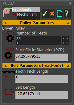
STEP 4: Edit the Driven Pulley
1.Double-click a Pulley
The Pulley dialog is now open
2.Edit the Number-of-Teeth
3.Close the Pulley dialog . |
Save your model - CTRL+S
|
 Kinematics-Tree - Pulley
Path-Joint |
The Driven-Pulley is a Pulley-Rocker
|
The Driving-Pulley is a Rocker.
Important:
The Driving-Pulley does not need to be a Rocker. It can be one Part in a Dyad that rotates. It must be a Part that:
•rotates, ...
•... with a Pin-Joint at the center of the Arc on the sketch-path, ...
•... and is kinematically-defined. |
|