Fixed Pulleys centers: Pulleys driven by a Belt
This design arrangement is a little more unusual than the Belt driven by a Pulley.
Physically, the Belt is wrapped around freely rotating Pulleys. The Belt is driven by motion-values at the input-connector to the Motion-Path FB.
 Sketch Path for Belt |
STEP 1: Add a closed sketch-path to represent the path of the belt.
1.Edit the Base-Part :
a)Add a sketch-path to represent the path of a Belt . In this example, the sketch-path has two Arcs and two Lines. . In this example, the sketch-path has two Arcs and two Lines.
b)Click : Click each Arc  . The radius of each Arc is not important. . The radius of each Arc is not important.
c)Click Click the center-Points of the Arcs . The distance between the Arcs is not important . The distance between the Arcs is not important
2.Exit the Part-Editor |
STEP 2: Add a Line to the sketch
1.Edit the Base-Part
a)Click - drag in the graphics-area to add the Line . .
b)Click : Click the start-Point of the Line and the center-point of an Arc.
c)Click : Click the Line
d)Click : Click the Line
2.Exit the Part-Editor |
|
 Command-Manager:
Add Motion-Path FB |
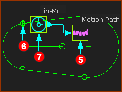
STEP 3: Add a Motion-Path FB
1.
2.Click the sketch-element in the sketch-path that represents the belt.
3.Click  in the Command-Manager in the Command-Manager |
A Motion-Path FB is in the graphics-area and a Motion-Point is in the graphics-area and a Motion-Point is at the start-Point of the sketch-element that you select. is at the start-Point of the sketch-element that you select.
The symbol for the Motion-Point is a small triangle inside a small Point symbol.
|
|
|
STEP 4.Add a Linear-Motion FB and connect to the Motion-Path FB
1.Click the
2.Click the graphics-area
3.Connect a wire from the Linear-Motion FB to the Motion-Path FB. to the Motion-Path FB.
4.Drag from the output-connector of the Linear-Motion FB to the input-connector of the Motion-Path FB |
A Linear Motion FB is in the graphics-area, and it is connected with a wire to the Motion-Path FB.
Motion-values at the output of the Linear-Motion FB are 0 – 360. The Data-Type is Rotary.
In one machine-cycle, 0 – 360 from the Linear-Motion FB can move the Motion-Point along the total length of the sketch-path.
|
|
|
STEP 4: Add the Parts for the Pulley's
The two Parts are not kinematically-defined. They are free to rotate.
|
 Command-Manager |
STEP 1: Add Pulley 1

|
1. |
opens in the Command-Manager.
You must select four elements
1.Click a Pin-Joint
2.Click the Motion-Path FB
The Part-Editor opens to show the sketch-path of the Belt in the Base-Part
3.Click the radius Dimension of the Arc sketch-element at the Pin-Joint
The Part-Editor closes.
4.Click the Part that has the Pin-Joint
5.Click  to close the Command-Manager. to close the Command-Manager. |
STEP 2: Add Pulley 1
Do Step 1 again for the other rotating Parts.
|
|
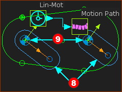
 Two Pulleys Driven by the Belt' |
Driven-Pulleys.
The linear-velocity of a Belt controls the angular-velocity of a Pulley.
•When you add a Pulley, the radius of the Arc in the sketch-path will change to give an integer number-of-teeth on the Pulley.
•Driven-Pulleys are Purple
•Edit the number-of-teeth with the Pulley dialog.
•Edit the Tooth-Pitch in the Motion-Path FB. |
|
 Kinematics-Tree - Pulley
Path-Joint |
Thee are two Driven Pulleys are in the model.
In the Kinematics-Tree they are Pulley-Rockers
|