1 Driving-Pulley, multiple Driven-Pulleys

<< Click to Display Table of Contents >>

Navigation:  Getting Started Tutorials - MechDesigner > Tutorial 17: Belts and Pulleys > Step 17.2: Option 1 - Fixed Pulley Centers >

1 Driving-Pulley, multiple Driven-Pulleys

Fixed-Center Pulleys

We will add a Multi-Pulley and Belt system.

We can define the motion of ZERO or ONE Pulley. In this model we will define the motion of ONE Pulley. THe motion of the others are found from the velocity of the Belt.

We will edit the Number of Teeth on each Pulley

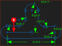
We will edit the Length of the Belt with Controlling Dimension, using the Target Belt Length parameter.

Preparation

GST-17-1-MultiP-A

STEP 1: Add a closed sketch-path (sketch-loop) to represent the Path of the Belt

1.Edit the Base-Part

2.Part-Editor: Add a sketch-path with more than two Arcs

3.Part-Editor: Add a dimension to each Arc. The exact radius of the Arc is not important.

The Belt will be Driven by a Driving-Pulley, which will be a Rocker.

4.Part-Editor: Add a LineRed-14-1b - its start-Point is merged or coincident with the center-point of an Arc.

5.Close the Part-Editor

GST-17-1-MultiP-B

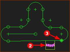
STEP 2: Add Motion-Path FBRed-14-2  

1.Click Kinematic FB toolbar > Add Motion-Path FB

The Command-Manager has one selection-box

2.Select the sketch-path that represents the belt.

3.Click OK-tiny-13-17 to close the Command-Manager

The Motion-PointRed-14-3 is at the start-Point of the sketch-element you select in the sketch-path.

GST-17-1-MultiP-C

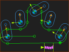
STEP 3: Add a Rotating-Part for each Pulley.

1.Add one Part for each Pulley

2.Add one Pin-Joint to join the start-Point of the Part to the center-Point of an Arc

The length of each Part is not important.


GST-17-1-MultiP-D

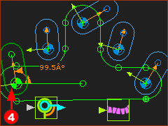
STEP 4: Add a Motion-Dimension FB to the Part you wish to be the Driving-Pulley.

Click Kinematic FB toolbar > Add Motion-Dimension FB

Click the Pin-JointRed-14-4 at the start-Point of the LineRed-14-1b in the sketch

Click the Line

Click the CAD-Line along the Part to be the Driving-Pulley.

A maximum of one kinematically-defined Part can be a Driving-Pulley.

Do Add Pulley

GST-GA-CM-AddPulley-Multiple-05

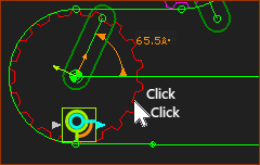
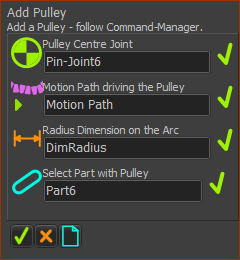
STEP 1: Start the Add Pulley command

GST-Icon-AddPulley

1.Machine elements toolbar > Add Pulley

Add Pulley opens in the Command-Manager.

STEP 2: Select the elements

Do Add Pulley to the rotating-Part that is kinematically-defined (the Rocker)

1.Click the Pin-Joint

2.Click the Motion-Path FB

The Part-Editor opens with sketch-path to which you add the Motion-Path FB

3.Click the radius Dimension of the Arc

The Part-Editor closes

4.Click the Part joined with a Pin-Joint at the center of the Arc.

Click OK-tiny-13-17 in the Command-Manager.

The Driving-Pulley is in the model.

GST-17-1-MultiP-E

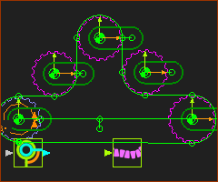
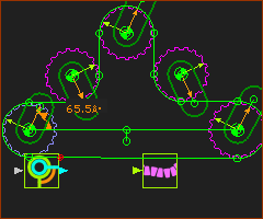
STEP 3: Add four more Pulleys

Do STEP 1 and STEP 2 four more times.

A total of five Pulleys are in the model

There is one Driving-Pulley and four Driven-Pulleys.


Notes: Colors of the Pulleys:

Driving-Pulleys are Lilac

Driven-Pulley are Magenta

Use Edit Pulley dialog

GST-17-1-MultiP-F

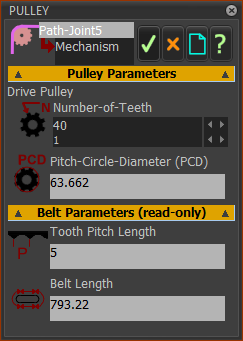
Edit the Number-of-Teeth on a Pulley.

Open the Pulley dialog

1.Double-click a Pulley in the graphic-area

or

See How to open a dialog


GST-DIALOG-PULLEY

In the Pulley dialog

Edit the Number-of-Teeth

Repeat 1 and 2 for each Pulley.

GST-17-1-MultiP-G

3.Edit the Motion-Dimension FB to 0º .

When the Driving-Pulley is at 0º, the other Pulleys will also be at 0º.