Step 1.2: Add a Part

<< Click to Display Table of Contents >>

Navigation:  Getting Started Tutorials - MechDesigner > Tutorial 1: Add a Part that Rotates - a Crank >

Step 1.2: Add a Part

Objective of Step 1.2

Learn how to identify the Mechanism-Editor

Learn how to add a Part

Review the elements that are in a Part


Video

Tutorial 1, STEP 1.2: Add a Part


Make sure the Mechanism-Editor is active (and not the Model-Editor)
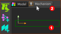
Click the Mechanism name-tab

Click the Mechanism name-tab

To make sure the Mechanism-Editor is active:

1.Click the Mechanism name-tabRed-14-2 at the top of the graphics-area

OR

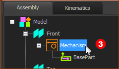
1.Click MechanismRed-14-3 in the Assembly-Tree (see image below)


Notes

In the Assembly-Tree, the Base-Part is a child to MechanismRed-14-3.

In the graphics-area, the symbol for the Base-PartRed-14-1b is a rectangular Part-Outline.

Click Mechanism in the Assembly-Tree

Click Mechanism in the Assembly-Tree

Add the Part

Drag to Add-Part

Drag to Add-Part

STEP 1: Start the Add Part command

GST-Icon-AddPart

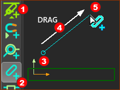
1.Expand the Kinematic-elements toolbar Red-14-1 - it is to the left of the graphics-area

2.Click the Add PartRed-14-2 command

OR

1.Keyboard Shortcut: Click the INSERT key on your keyboard

The mouse-pointer changes to Add Part.

To add the Part:

STEP 2: Drag in the graphics-area  

Do NOT click the graphics-area. If you do, you will need to start Add Part again.

Drag is:

Red-14-3 Mouse-button-down... to locate the start-Point of the Part

Red-14-4 ... move your mouse...

Red-14-5 ... mouse-button-up - to locate the end-Point of the Part

Parts and elements in the Mechanism-Editor
The new Part 

The new Part in the graphic-area

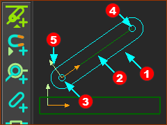
Parts you add to the model:

Red-14-1b The Part-Outline is oval - it is the symbol of a Part

Red-14-2 A CAD-Line is from the start-Point to the end-Point of an added Part

Red-14-3 start-Point of CAD-Line is where you mouse-button-down to add the Part.

Red-14-4 end-Point of CAD-Line is where you mouse-button-up.

Red-14-5 X-axis and Y-Axis - at the start-Point and on the Mechanism-Plane.

+X-axis direction from the start-Point to the end-Point of the CAD-Line.

+Y-axis direction from the start-Point, at 90º to the CAD-Line, and on the Mechanism-Plane.

+Z-axis direction from the start-Point, and uses the Right-Hand-Rule.

Use the CTRL+S keyboard shortcut to save your model.

See also Auto-Save

Drag in the graphics-area

You use the Drag mouse action to add many element-types. For example, to add a Part, a wire, a Line, an Arc, a Circle, a Blend-Curve, ...

Drag is always:

Mouse-button-down... to locate the start-Point of the element

... move your mouse...

  ... mouse-button-up - to locate the end-Point of the element