Objective of Step 1.3:
To learn •how to open and close the Part-Editor •how to add and delete a sketch-element, constraints and dimensions. •that some dimensions are negative - it is a MechDesigner rule! •that sketch-elements change their color when they are “fully-defined”. |
Video

Tutorial 1: STEP 1.3 Add Line to the Base-Part
Open the Part-Editor to edit the Base-Part.
You use the Part-Editor to add geometry* to a Part. * Geometry includes sketch-elements, constraints, and dimensions. |
||
 Double-click the Base-Part |
STEP 1: Open the Part-Editor Use the Double-click method:
The Base-Part is now open with Part-Editor. |
|
Details of a Part in the Part-Editor
 The Part-Editor |
The Base-Part - when it is open in the Part-Editor:
|
Add a Line to the Base-Part
|
STEP 1: Start the Add Line command
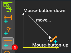
The Add Line command is active. Your pointer is now the Add Line pointer. STEP 2: Add the Line
The drag technique to add a Line is identical to that for Add Part. Reminder: Drag is...
The Line is now in the Part. |
||||
 Line in graphic-area |
Add Coincident Constraints
You can now add constraints and dimensions to locate the Line. Usually, add constraints before you add dimensions. |
|||||
|
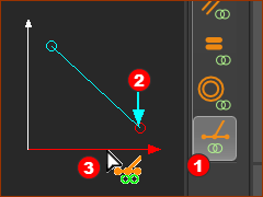
STEP 1: Start the Add Coincident Constraint command You want a Point* at the end of the Line to be on the X-axis of the Base-Part.
The Point now has a Coincident constraint with the X-axis. * start-Point or end-Point of the Line. |
||||
TOP-TIP
|
|||||
 Add Coincident Constraint  Drag Points along the Axes |
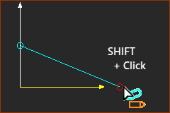
STEP 2: Add a Coincident constraint, again You also want to constrain a Point* at the other end of the Line to the Y-axis.
The Point now has a Coincident constraint with the Y-axis. * start-Point or end-Point of the Line. |
||||
STEP 3: Deselect Coincident Constraint
|
|||||
How to delete a Constraint
|
You cannot see constraints in the graphics-area. To delete a constraint
If you do delete the constraint, then to continue this Tutorial: •Add the constraint again! OR •Press the CTRL+Z key combination. |
|
 Shortcut menu |
Add Dimensions
 Select Point and X-axis to add a dimension  Dimension dialog |
STEP 1: Start the Add Dimension command
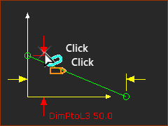
STEP 2: Add a Dimension
|
|||
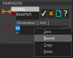
The Dimension dialog opens immediately STEP 3: Edit the dimension
|
||||
 Add a Dimension |
STEP 4: Add one more Dimension
The Line changes its color when the Line is fully-constrained. |
|||
 Note the Negative Dimension |
The Edit Dimension dialog opens immediately STEP 4: Edit the dimension
The dimension is 120mm in the sketch, not –120. See below: Why is the Dimension negative? Note, If the number is –100, you need to click the Left Spin-Box arrow to decrease the value to –120.
|
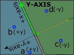
Why is the Dimension negative?
|
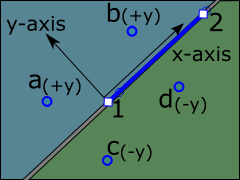
Coordinate System of a Line, or the Part's Y-axis. The X-axis and the Y-axis are treated as Lines when you select them to add a dimension. A Line has a coordinate system : an Origin, +X-axis, and a +Y-axis. •The origin of a Line's coordinate-system is its start-Point. •The +X-axis direction is from the Line's start-Point to its end-Point. •Its +Y-axis direction is +90º from the +X-axis, and on the Mechanism-Plane Important - the X-axis and Y-axis are also pseudo-Lines, and, therefore, they also have their own Coordinate-Systems. The +X-axis of the Y-axis is the Y-axis ! When we add a dimension between the Y-axis and Point: we must remember: •the dimension is positive when the Point is in the +Y-axis direction of the Y-axis •the dimension is negative when the Point is in the –Y-axis direction of the Y-axis In top image, when we click the X-axis and then a Point that is below the X-axis (c or d in the green area), the dimension is negative. As expected. In bottom image, when we click the Y-axis and then a Point that is anywhere in the +X-axis area (c or d in the green area), the dimension is negative. Less expected! |
|
To edit a Dimension
When you add sketch-elements and dimensions, you also need to edit dimensions. You cannot edit a dimension if a command is active - even if Add Dimension is the active command. STEP 1: Clear all Commands
|
|||||
|
STEP 2: Edit the Dimension
The Dimension dialog is open. STEP 2.Edit the Dimension
|
||||
Close the Part Editor
You must close the Part-Editor to return to the Mechanism-Editor. |
|||
 Close the Part-Editor  Right-click in graphic-area |
STEP 1: Close the Part-Editor There are many methods you can use to close the Part-editor. For example:
|
||
 Edit Part in Part-Editor command |
You are now in the Mechanism-Editor again. Save your Mechanism with CTRL+S |
||
Colors of Sketch-elements in the Part-Editor and Mechanism-Editor
See Application-Settings > Graphics tab > Graphic Colors:
Geometry Fully Defined, Geometry Under Defined, Part Solved, and Part Not Solved.
 The Line in the Mechanism-Editor |
The default colors of a sketch-element (for this Dark Charcoal Theme) in the Part-Editor:
The color of sketch-elements in a Part after you close the Part-Editor. are the same color as the Part-Outline of the Part to which you added the sketch-elements. That is, in a Mechanism-Editor:
* We will discuss the colors of a Part-Outlines in Step 1.5. |
||
The Base-Part and sketch-elements.
|
|||