Objective of Step 1.6
To understand: •the basics of how to use Function-Blocks •how to connect wires between different Function-Blocks •how to delete wires between Function-Blocks •how to move a Part with Constant Angular Velocity - or Uniform Rotary Motion |
See also: How to Connect Function-Blocks
Terminology:
Term : |
Definition |
|---|---|
Motion-Part : |
A Part whose position relative to a different Part you control with a Motion-Dimension FB. |
Rocker : |
A Motion-Part that rotates with a non-uniform rotary motion. |
Crank : |
A Rocker that rotates with a uniform angular velocity. |
a Part that is kinematically-defined : |
A part whose state is solved. It has a Mobility of zero. You can plot its position, velocity, and acceleration motion-values. |
FB : |
Abbreviation of Function-Block |
Connect a wire : |
Drag a wire from the output-connector of one Function-Block to the input-connector of a different Function-Block. |
Motion-Values : |
Displacement, velocity, and acceleration data that flows through Function-Blocks and along the wires that connect Function-Blocks. |
Video

STEP 1.6: Rotate the Part
Schematic 'wiring-diagram' of Kinematic Function-Blocks
 |
•We use Kinematic Function-Blocks to transfer motion-values to Motion-Parts and Motion-Points •You connect wires from the output-connector of a Function-Block to the input-connector of a different Function-Block The schematic diagram, to the left, attempts to show how you can connect wires between different types of Function-Blocks. |
Motion-Providers: have output-connectors. The motion-values are either equal to the MMA or the motion is from the motion measurement of a Part or Point in a kinematically-defined chain. Motion-Processor: use the motion-values from Motion-Providers as the independent variable for their internal function. Motion-Part: identified by a Motion-Dimension FB. Control its motion with motion-values at the input-connector to the Motion-Dimension FB. Motion-Point: identified by a Motion-Path FB. Control its motion with motion-values at the input-connector to the Motion-Path FB. |
|
Tutorial Steps:
Add a Linear Motion FB; Connect a wire to the Motion Dimension FB
|
STEP 1: Select the Linear-Motion FB.
|
|||
|
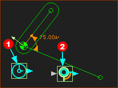
STEP 2: Click in the graphics-area.
The Linear-Motion FB
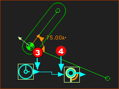
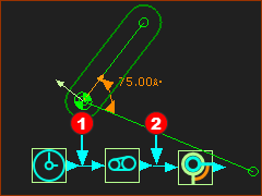
STEP 3: Connect Function-Blocks with wires.
STEP 4: Cycle the kinematic-chain.
|
|||
|
||||
|
||||
Summary:
|
||||
Rotate the Part in a Clockwise direction
When we increase the angle of a Motion-Dimension, we rotate a Motion-Part in the counter-clockwise direction. Because the motion-values at the output from the Linear-Motion FB always increase, the Crank also rotates in the counter-clockwise direction (the direction of increasing angles). |
|||
|
To rotate the Crank in a negative or clockwise direction: STEP 1: Add a Gearing FB
The Gearing FB is now in the graphics-area. |
||
|
STEP 2: Delete the wire between the Linear-Motion FB and the Motion-Dimension FB
STEP 3: Connect wires between the three Function-Blocks
|
||
 Gearing FB dialog > Gearing-Ratio |
STEP 4: Edit the Gearing dialog
STEP 5: Cycle the kinematic-chain.
The Crank now rotates in a Clockwise direction. |
||
Other Notes
Master Machine Angle (MMA)
Master Machine Angle Scale in the Feedback Area
|
Revs: (read-only) a counter for each time the machine angle cycles from 0 to 360 Pointer (▲): below the MMA scale ; the approximate value of the Master Machine Angle Machine Angle (read -write) the exact value of the Master Machine Angle To edit the value of the Master Machine Angle Approximately : Drag, to the left or right, with your mouse-pointer in the MMA scale. Exactly : Edit the value in the Machine Angle box. |
Animation Speed
Animation Speed Slider Scale in the Feedback-Area |
Edit the Animation-Speed The Animation-Speed does not change kinematic results. •Drag to the left or right with your mouse-pointer in the Animation-Speed Slider Scale. Edit the Simulation-Speed The Simulation-Speed does change the kinematic results. •Edit the simulation-speed with Edit menu (or toolbar) > Machine Settings > Cycles / Minute (RPM) |