Objective of Step 1.7:
•To use the different methods to open the Part-Editor.
•To use the Part-Editor to edit the length of the . |
Video
Edit the length of a Part
You will probably find you use of these methods to start the Part-Editor. Occasionally, you will need to use a different method.
METHOD 1: Use the Selection-Window
 Click the Part-Outline (or Y-axis)
|
STEP 1: Click the Part-Outline
1.Click the ONE-TIME - see image
or
1.Click the Y-axis of the Part ONE-TIME
OR
1.Click the Part element in the Assembly-Tree ONE-TIME
If the Part-Outline is near to other elements, you may also click those elements.
|
All of the elements you click are in the .
|
 Shortcut menu in Selection-Window
|
STEP 2: Edit the element from the Selection-Window
In this case, we want to edit the Part element (to start the Part-Editor)
1.Identify the Part element in the Selection-Window 
2.Right-click the Part element in the Selection-Window 
A shortcut menu is next to your pointer.
3.Click Edit Element in the shortcut-menu  |
|
METHOD 2: Double-click
 Double-Click Part-Outline (or Y-axis)
|
STEP 1: Double-click in the graphics-area
1.Double-click the Part-Outline in the graphics-area
OR
2.Double-click the Y-axis of the Part |
IMPORTANT:
Occasionally, with some graphic-cards, you must double-click the arc of the Part-Outline near to the start-Point to edit a Part.
You may find it easier to double-click the Y-axis of the Part you want to edit.
|
 Double-Click Part in Assembly-Tree
|
Or
1.Double-click the Part element in the Assembly-Tree |
|
METHOD 3: Use Edit menu > Edit Part in Part-Editor / Edit-Part icon in toolbar
 Edit Part in Part-Editor
|
STEP 1: Preselect Part-Outline

|
1.Click a Part-Outline
2.Click (left of graphics-area) |
OR
STEP 2: Preselect Edit Part in Part-Editor

|
1.Click (left of graphics-area)
2.Click a Part-Outline
3.Click the graphics-area |
|
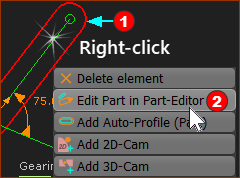
METHOD 4: Right-Click in the graphics-area or Assembly-Tree

|
STEP 1: Right-click the Part-Outline
1.Hover (do not click) over the Part-Outline so that it is the
2.Right-click the Part-Outline in the graphics-area
You will see a shortcut menu.
3.Click Edit Part in Part-Editor (MD 17- Toggle “Part-Editor” ) n the shortcut menu. |
|
|

|
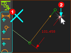
Note: You cannot edit a dimension when a different command is active 
METHOD 1: Use the Selection-Window
Make sure all commands are NOT selected 
1.Click the dimension-line, the arrowhead of the dimension-line, or the extension-line.
The arrowhead is the easiest.
The Dimension should now be in the Selection-Window.
2.Right-click the dimension element in the Selection-Window
3.Click Edit Element in the shortcut-menu |
The Dimension dialog is now open.
METHOD 2: Double-click the Dimension-Line
Make sure all commands are NOT selected 
1.Double-click the dimension line, dimension-line arrowhead, or extension line
The arrowhead is the easiest
See
|
The Dimension dialog is now open.
|

|
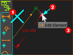
METHOD 3: Right-click the Dimension-Line
Make sure all commands are NOT selected 
1.Right-click the dimension line, dimension-line arrowhead, or extension line
The arrowhead is the easiest
2.Click Edit Element in the shortcut menu |
The Dimension dialog is now open.
|
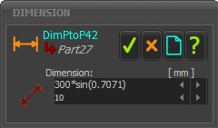
There are three methods to edit a parameters value.
METHOD 1: Use your Keyboard
 Dimension dialog
|
Enter a data-value directly:
1.Enter the data-value with your keyboard
2.Press the Enter key on your keyboard to update to the new value
You must press the Enter key (also called the Return key) to update the value.
|
|

|
Enter a symbolic equation:
1.Enter the data-value with your keyboard
2.Press the Enter key on your keyboard to update to the new value
You must press the Enter key (also called the Return key) to update the value.
|
|
Symbolic parameters:
•Simple Arithmetic: +, –, *, /;
•Indices: ^, Sqrt();
•Trigonometric (Angles are Radians), pi, Sin(), Cos(), Tan(), Sinh, Cosh, Tansh, ArcSin(), ArcCos(), ArcTan2( ; ) |
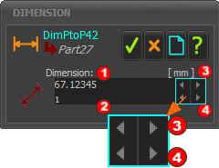
METHOD 2: Use the 'Spin-Box' tool

|
Spin-Box arrow buttons (in the blue-box)
Top : Left arrowhead to decrease the data-value by the Spin-Increment
Top : Right arrowhead to increase the data-value by the Spin-Increment
Bottom : Left arrowhead to divide the Spin-Increment by 10
Bottom : Left arrowhead to multiply the Spin-Increment by 10
|
Edit the Data Value
•Click the Top : Left arrowhead to decrease the data-value . (Data-value after one click: 67.12345 – Spin-Increment(1) = 66.12345 )
•Click the Top : Right arrowhead to increase the data-value (Data-value after one click: 67.12345 + Spin-Increment(1) = 68.12345 )
Edit the Spin-Increment
•Click the Bottom : Left arrowhead to decrease the spin-increment (Data-value after one click: 1 ÷ 10 = 0.1 )
•Click the Bottom : Right arrowhead to increase the spin-increment (Data-value after one click: 1 × 10 = 10 )
WARNING: The model re-builds each time you click the top arrow-buttons of the Spin-Box tool
|

|
< >
Double-Click
|

|
Double-click inside the data-box to hide the Spin-Box.
Double-click the data-box again to show the Spin-Box.
|
|
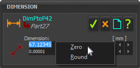
METHOD 3: Use the shortcut-menu

|
1.Right-click inside the data box
The Zero / Round / Copy / Paste shortcut menu shows.
•Zero: - do not use for dimensions
•Round: change the value to the nearest value that is exactly divisible by the Spin-Increment. |
|
 3 Methods to Close the Part-Editor
|
To close the Part-Editor, use one of these 3 methods:
1.Double-click the Y-axis* or a
or
1.Cancel Edit Part in Part-Editor (MD17: Toggle “Part-Editor”) to the left of the graphics-area
or
1.Right-click in the graphics-area
2.Click Edit Part in Part-Editor (MD17: Toggle “Part-Editor”) icon in the shortcut menu |
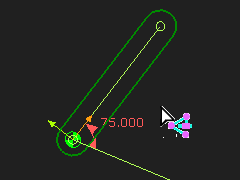
* Why the Y-axis?
Because, if you double-click the X-axis, you may actually double-click the CAD-Line and open the CAD-Line dialog.
When you return to the Mechanism-Editor:
The X-axis and Y-axis are small.
Note:
•The Part is 70 long.
•Base-Value of the Motion-Dimension is 75°. |

|
URL of this topic:
http://mechdesigner.support/index.htm?gst-1_7-edit-length-of-part.htm