Objective of Step 1.5:
To understand: •that Parts have two kinematic-states. Parts are “kinematically-defined” or “not kinematically-defined”. •that Parts must be kinematically-defined before you can analyze their kinematics. •that a Part-Outline has two colors, and that the color indicates kinematic-state of a Part. •how to add a Motion-Dimension FB* to control the angle of a Line in a Part relative to a Line in a different Part. •that a Motion-Dimension FB changes the kinematic state of a Part. To explore elements in the Kinematic-Tree. * FB = Function-Block |
IMPORTANT
A Part has two kinematic states. Either ... a Part is not kinematically-defined OR ... a Part is kinematically-defined Parts need to be kinematically-defined before you can analyze their kinematics. * To edit the colors, use Application-Settings dialog > Graphics tab > Display Colors > “Part Solved” / “Part Not Solved”. Solved = kinematically-defined / Not Solved = not kinematically-defined. We recommend that you use colors that are approximately green and approximately blue. |
Video

Tutorial 1 STEP 1.5: Add Motion-Dimension FB
| Add a Motion-Dimension FB to kinematically-define a Part. |
Kinematic State of the Parts after STEP 1.4, and before we do STEP 1.5
You can drag the Part-Outline (and Part) to rotate the Part around the Pin-Joint. The Part has one Degrees-of-Freedom. |
|||
 AAdd Motion-Dimension FB |
STEP 1: Start the Add Motion-Dimension FB command
The Command-Manager starts. |
||
|
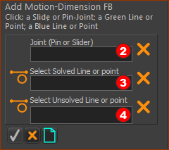
The Command-Manager has three selection boxes. The element-types you can click to fill the selection-boxes are:
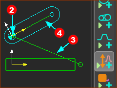
* Solved Line or Point = a Line or Point in a Part that is kinematically-defined ** Unsolved Line or Point = a Line or Point in a Part that is not kinematically-defined STEP 2: Select the three elements to Add Motion-Dimension FB
* there is a CAD-Line from the start-Point to end-Point of all Parts you add to the model |
||
|
|||
 Commandd Manager with selections |
STEP 3: Complete the command
|
||
|
Result
Note: The Motion-Dimension FB element has two features. There is the:
|
||
Edit the Base-Value parameter in the Motion-Dimension dialog. The Base-Value is an offset value of the angle relative to the Line you added to the Base-Part. |
|||
 Motion-Dimension FB dialog |
STEP 1: Open the Motion-Dimension dialog
The Motion-Dimension dialog is now open. In the Motion-Dimension dialog > Base and Motion Angle STEP 2: Edit the Parameters
Directions It is possible to negate the Base-Value and the Motion-Value.
|
||
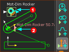
In the graphics-area, the Motion-Dimension FB has two features. The: A: FB - the icon B: Dimension Value, Line, and Arrowheads of the Motion-Dimension |
|
 MOVE the Mot-Dim FB = DRAG FB |
Please read carefully In the graphics-area, ... To move the FB ...Drag the FB The FB moves from
|
 MOVE the Dimension Line/Arrowheads |
In the graphics-area... To move the Dimension Value, Line, and Arrowheads of the Motion-Dimension CTRL + Drag the FB The Motion-Dimension snaps to your mouse-pointer, from |
Click the Kinematics-Tree tab, next to the Assembly-Tree, Explore “Mechanisms” and “Kinematic-Chain” in the Kinematics-Tree. |
||
The Part, Pin-Joint, and Motion-Dimension are the elements of a Rocker. A Rocker is a Motion-Part. |
||
 Kinematic-Tree with Elements for a Rocker |
|
Part |
|
Pin-Joint |
|
|
Mot-Dim Rocker |
|