Motion from MotionDesigner
When we connect a Linear-Motion FB to the Motion-Dimension FB (see Step 1.6 ), the Motion-Part rotates with uniform angular velocity. A Gearing FB can change the angular velocity. However, Parts in packaging machines frequently have complex motions. You can design complex motions in MotionDesigner. You use a Motion FB to link a complex motion in MotionDesigner to a Motion-Part in the model. |
Objective of this Step
1.Control how a Part moves with a Motion FB. 2.Show the Kinematic-Vectors for a Point. |
Summary of this Step
1.Delete the Gearing FB between the Linear-Motion FB and the Motion-Dimension FB. 2.Add a Motion FB to the graphics-area. 3.Connect a wire from the Linear-Motion FB to the Motion FB and from the Motion-FB to the Motion-Dimension FB. 4.Edit a Point to show its Kinematic Vectors. 5.Edit the scale (length) of the Kinematic Vectors. You should also complete MotionDesigner Tutorials 2 and Tutorial 3 to change the motion design. |
Video of this Step

Add Motion FB, Edit Motion-Dimension FB
Add a Motion FB
|
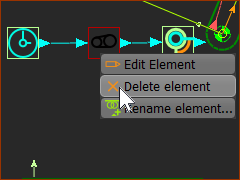
STEP 1: Delete the Gearing FB
|
||
|
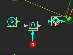
STEP 2: Add a Motion FB
The Motion FB We automatically link for you the motion in the left-most Motion name-tab to the Motion FB. To link a different motion, you must edit the Motion FB. |
||
|
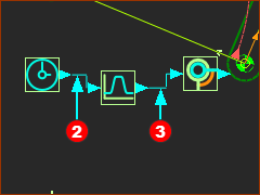
STEP 3: Connect wires between the Function-Blocks See also: How to connect wires between FBs
In the image, there is wire STEP 4: Cycle the kinematic-chain
|
||
More details:
|
|||
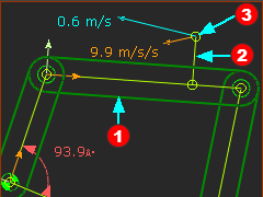
Instant Analysis: Kinematic Vectors
MechDesigner calculates the Position, Velocity, and Acceleration of all Points* at all times. * Points, start-Points, end-Points, and center-Points. |
|||||||
|
STEP 1: Add a Line to the Coupler Edit the Coupler Part
You can see the Line |
||||||
 Point Properties dialog |
STEP 2: Show the Velocity and Acceleration Vectors:
|
||||||
Change the scale of the Vectors in the graphics-area.
About the Velocity and Acceleration Vectors
Notes
|
|||||||