Objective of Step 2.3
To use different methods to delete an element. In this case, you delete a Pin-Joint.
To replace a Pin-Joint with a Slide-Joint.
Introduce the R-R-P dyad in the Kinematics-Tree.
|
Summary of Step 2.3
1.Delete a Pin-Joint with different methods.
2.Add a Slide-Joint
3.Review the Symbols that represent a Slide-Joint |
Video 1 - Delete Pin-Joint with different methods
Video: How to delete elements
Video 2 - Add Slide-Joint
Delete the Pin-Joint with the ...
You will use the shortcut menus to delete a Pin-Joint from the:
•
•
• |
... Selection Window
|
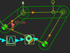
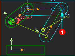
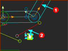
STEP 1: Select the Pin-Joint
1.Click the Pin-Joint in the graphics-area in the graphics-area |
Look in the Selection-Window.
It is possible, and even probable, that there is more than one element in the Selection-Window.
|
|
In this case, the Pin-Joint and two Points are in the Selection-Window.
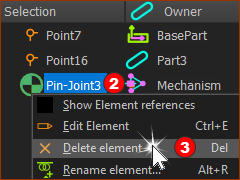
STEP 1: Delete the Pin-Joint with the shortcut menu
1.Right-click the Pin-Joint in the Selection-Window
The shortcut menu opens.
2.Click Delete element in the shortcut menu |
You delete the Pin-Joint.
|
|
The of the two Parts that were in the R-R-R dyad are now a different color - typically Blue.
The two Parts are now not kinematically-defined.
Kinematics-Tree
Explore the Kinematics-Tree.
•Kinematic-Chain - the Rocker only
•Unsolved Mechs -
Unsolved Mechs are the two Parts and two Pin-Joints.
Degree-of-Freedom (DOF) = 2
2 × Parts=6, - 2 × Joint=4 : 6 – 4= 2
Not kinematically-defined.
|
|
 Kinematic-Tree with Unsolved Mechs |
... Assembly-Tree
|
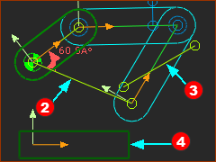
STEP 1: Replace the Pin-Joint
Click
or
1.Do the CTRL + Z shortcut key combination
or
1.Click | Click the two Points again |
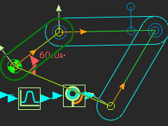
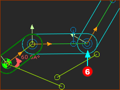
In the graphics-area, the Pin-Joint is in the model again.
The Parts are kinematically-defined again - and Green.
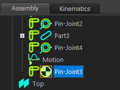
STEP 2: Select the Pin-Joint
1.Click the Assembly-Tree
2.Find the Pin-Joint that you want to delete
When you click different elements in the Assembly-Tree, they are also selected (and Red) in the graphics-area.
|
A Pin-Joint has two different symbols:
 The element symbol of a Pin-Joint that joins a Part to the Base-Part The element symbol of a Pin-Joint that joins a Part to the Base-Part
 The element symbol of a Pin-Joint that joins a Part to a different Part that is not the Base-Part. The element symbol of a Pin-Joint that joins a Part to a different Part that is not the Base-Part.
|
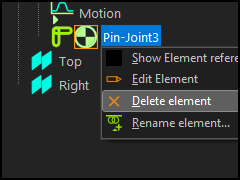
STEP 3: Delete the Pin-Joint - again
3.Click the Pin-Joint in the Assembly-Tree - there is an Orange square around the symbol for the Pin-Joint -
4.Right-click the Pin-Joint in the Assembly-Tree
5.Select Delete element in the shortcut-menu. |
The of the two Parts are a different color - typically Blue.
The two Parts are not kinematically-defined.
|
|
|
|
... Kinematics-Tree
|
STEP 1: Replace the Pin-Joint
Click
or
1.Do the CTRL + Z shortcut key combination
or
1.Click | Click the two Points again |
In the graphics-area, the Pin-Joint is in the model again.
The Parts are kinematically-defined again - and Green.
|
|
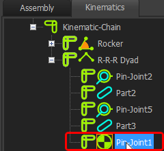
STEP 2: Delete the Pin-Joint - again!
1.Click the Kinematics tab in the Project-Explorer to open the Kinematics-Tree.
2.Expand the Kinematic-Chain and the R-R-R dyad.
You can see the list of three Pin-Joints and two Parts.
3.Click the Pin-Joint in the Kinematics-Tree - there is Orange square around the Pin-Joint symbol
4.Right-click the Pin-Joint
5.Select Delete element in the shortcut-menu.
When you click an element in the Kinematics-Tree, its color changes in the graphic-area, also, to show it is selected.
|
|
|
The of the two Parts are a different color again - typically Blue.
The two Parts are not kinematically-defined.
|
A Slide-Joint.
 Slide-Joint in MechDesigner |
 Slide-Joint - THK |
 Slide-Joint in SOLIDWORKS |
A is between two Lines.
•The Lines are collinear with each other.
•Each Line is a child to a different Part
Imagine Line 1 (on Part 1) as a Slide-Rail, and Line 2 (on Part 2) as the Slide-Block.
|
Prepare to add the Slide-Joint
Add a Line to the Base-Part
We will add a between the CAD-Line in a Part and a Line we add to Base-Part.
 New Line in Base-Part |
STEP 1: Add a Line to the Base-Part.
1.Double-Click the rectangle that is the Part-Outline of the Base-Part.
The Part-Editor is open.
The Line (see Step 1.3) has been moved up by 50
2. | Drag* to the right (>) and up (^) to add the Line
3. to control the position of the Line.
To exit the Part-Editor:
4.Double-click a sketch-element. E.g. Double-click the new Line. |
Now in the Mechanism-Editor, you can see the:
•new Line, and the:
•original Line
They are in the Base-Part . .
|
|
|
Colors of Part-Outlines and Colors of Sketch-Elements in when viewed in a Mechanism-Editor.
In the Mechanism-Editor, the default colors of sketch-elements in a Part are the same color as the Part-Outline.
The default colors of Part-Outlines are:
A type of Green when the Part is kinematically-defined - the Part is Solved
A type of Blue when the Part is not kinematically-defined - the Part is not Solved.
Therefore, sketch-elements and the Part-Outline of the Base-Part are Green because the Base-Part is kinematically-defined/solved.
See Application-Settings>Graphics tab>Display Colors> Part Solved / Part Not Solved
|
|
Delete and add a Pin-Joint (again!)
Why again?
We do not need to Delete and Add a Pin-Joint! But it will help when we do Step 2.5
|
|
STEP 1: Delete a Pin-Joint
1.Click the Pin-Joint at the end of Part that was the Coupler and Rocker.
The Pin-Joint should be in the Selection-Window.
2.Click the Pin-Joint.
3.Click the Delete key on your keyboard. |
|
|
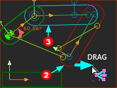
STEP 2: Move the Part that is Completely Free
Before we can add a new Pin-Joint, we must move a Part so that we can identify the Points we need to select for the new Pin-Joint.
Part is completely-free (zero Joints)
Part is a free (one Joint)
1.Drag Part that is completely-free. |
|
|
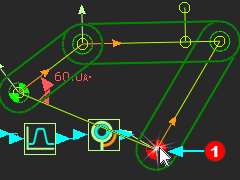
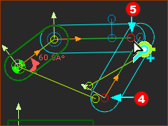
STEP 3: Add a new Pin-Joint
|
|
RESULT
The new Pin-Joint is in the graphics-area. is in the graphics-area.
The Part has moved.
The Parts are not kinematically-defined.
|
|
Add the Slide-Joint
|
STEP 1: Start the Command

|
1.Expand the
2.Click |
The pointer changes to .
|
STEP 2: Select the Elements
You must click two Lines to add a Slide-Joint:
3.Click the CAD-Line along the Part
4.Click the Line in the Base-Part |
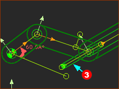
Result
The Slide-Joint is in the graphics-area.
The two Parts are kinematically-defined.
There is a new dyad in the Kinematics-Tree - the R-R-P dyad - see below.
|
|
|
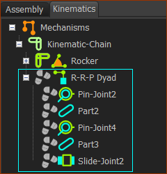
Kinematics-Tree and the R-R-P dyad
|
Expand the Kinematics-Tree
•1 × Kinematic-Chain
•1 × Rocker
•1 × R-R-P dyad
The three Joints in the R-R-P dyad are:
•Two Revolute-Joints, (R-R-P) - two Pin-Joints
•One Prismatic-Joint (R-R-P) - one Slide-Joint |
|
The Symbols that represent a Slide-Joint
 A Slide-Joint and sliding-Part |
The symbols that represent a .
A Wide rectangle along a Line used for the Slide-Joint
A Narrow rectangle along the other Line used for the Slide-Joint
A small arrowhead at the start-Point of one of the Lines that you select for the Slide-Joint.
The Positive Direction of sliding-Part is in the direction of the arrowhead.
The Positive Direction is important if you want to control the motion of the sliding-Part with a Motion-Dimension.
|
|