Kinematic Analysis Tools
You can plot kinematic values for one or more machine cycles with a Graph FB.
You can also get kinematic values at the Master Machine Angle.
Objective of Tutorial 2C
To learn some (not all) of the different ways to get information from a model. |
The Element Properties dialog shows the kinematic values for an element at the Master Machine Angle. Elements that have Element-Properties are: •Part, Pin-Joint, Slide-Joint, 2D-Cam, Part-Outline, Line, Circle, Arc, Point, Gear-Pair, Function-Blocks, Wire, ... |
||
|
To show the Elements Properties dialog: Before MD16.1.370 In the graphics-area: CTRL + CLICK one element The Element-Properties dialog is now open. Note: The Element-Properties dialog does not open if you CTRL+Click more than one element. After MD 16-1-370 When you move your mouse above an element in the graphics-area, the Element's Properties shows in the Feedback Area > Extended Hints box You can choose not to show the Element Properties - see Application-Settings. |
|
 Element-Properties dialog-box : Point |
||
Example: Element-Properties of a Point. In this case, the Element-Properties are of Point212' Properties of a Point
|
||
A Trace-Point is the path of a Point* on the Mechanism-Plane for one machine-cycle. You can add and show many Trace-Points.
|
||||
Video : Add Trace-Point
|
||||

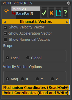 |
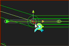
You can show the Kinematic-Vectors of a Point* with the Point Properties dialog. * Point, start-Point, end-Point, center-Point, Motion-Point. STEP 1: Select the Point
STEP 2: Enable the Velocity and or Acceleration Vectors
|
|||
Velocity and Acceleration Vectors in the graphics-area
Scope
Velocity Vector Options
Note 1: If necessary, change the color of the Vectors to see the Vectors and their kinematic-values more clearly - see Application Settings > Graphics tab > Display colors |
||||
 |
Top-Tip - make the vectors very short to see the magnitude of the vectors near to the Point. Use the Vector Scale buttons at the below the graphics-area. |
|||
 Velocity and Acceleration buttons. |
To change the length of vectors: 1.Click the up/down button to increase/decrease the length of the vector. |
|||
DO NOT USE UNTIL FURTHER NOTICE. To show the Dimensional Instant Radar Scale: In the graphics-area: ALT+Click The Instant-Scale shows next to your mouse-pointer. As you zoom-in or zoom-out the scale also auto-scales. There are 10 concentric circles. There are two thick circles, which show the actual dimension value at their radii. •Inner Dark Circle (50.000 in the image) is circle #5 •Outer Dark Circle (100.000 in the image) is circle #10 Linearly interpolate the dimensions for the other circles. Note: If the numbers have too may zeros, the inner number overwrites the outer number. You should reduce the number of digits. To reduce the number of zeros: Application-Settings > Number-Format. |
|
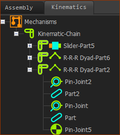
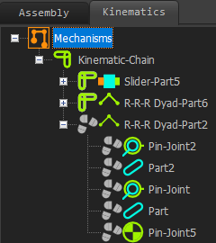
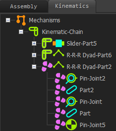
MechDesigner compiles Parts and Joints into dyads. Dyads have two(2) Parts and three(3) Joints. You may find that the two Parts assemble correctly when you add the last joints. But, when you cycle your model, you may find that Parts cannot assemble at all points in the machine-cycle. The Kinematics-Tree indicates to you whether the dyads can assemble or not.
The Kinematics-Tree uses symbols to indicate three KINEMATIC STATES.
KINEMATIC-STATE 1
|
 |
KINEMATIC-STATE 2
|
 |
KINEMATIC-STATE 3
|