Background to the Complications
 A typical rotating-Cam |
A Rotating Cam-Shaft. Typically, a cam and cam-shaft rotate once per machine cycle. The contact-point moves steadily along the Cam-Profile as the MMA increases from 0 to 360. The Cam-Profile does not self-intersect or repeat (unless there is undercutting). |
 A typical Slot-Cam |
A Slot-Cam However, with a Slot-Cam, the contact-point moves forwards and backwards along the Cam-Profile in one machine-cycle. The contact-point may also reverse its direction anywhere along the slot. This creates a problem: SolidWorks cannot create a Curve feature if Points in table are equal to each other. This topic describes how to solve this problem. |
There are two types of complication: A.The contact-point changes direction, or dithers*. In MechDesigner, when the Follower changes its direction, the contact-point moves from one Cam-Flank to the other Cam-Flank. * Dithers : small directional changes. B.The contact-point is stationary When the Follower is stationary relative to the cam - usually at each end of the Slot-Cam - the contact-point also becomes stationary (of course). However, as the MMA increases, we continue to calculate for you the cam-coordinates. Thus, there are many repeating Cam-Coordinates When the cam-profile has a complication as described in A or B, or A and B, SOLIDWORKS cannot create the Curve feature. |
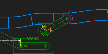 |
 VIDEO: Slot Cam that changes directions and 'complications' |
Example of a cam with the two complications. Refer to the image above and the VIDEO. The sliding-Part moves horizontally. A connecting-rod joins the sliding-part to a point that has a complex motion. Thus, the sliding-part also has a complex motion. Each time the sliding-part changes its direction, the contact-point moves from one cam-flank to the other cam-flank You can see a line between the cam-flanks when the contact moves between the cam-flanks. SOLIDWORKS will NOT be able to create a Curve Feature with this Cam. |
 VIDEO: Slot Cam with complications and Linearized Model |
Before we export the cam to SolidWorks, we must remove the two complications. There are two ways: •Save the Cam-Coordinates to a text file, and manually edit the text file before you manually import them into SolidWorks as a Curve feature. It is difficult, but possible. •In MechDesigner, linearize the motion between the Cam and Follower. Linearize is the best option. |
To Linearize the motion of the Cam.We need two models - the Original-Model and a Dummy-Model. STEP 1: Measure the displacement range of the sliding-part in the original-model. Range = Maximum displacement – Minimum displacement We can use a Measurement FB to measure the displacement of the sliding-part - you only need to measure the Minimum and Maximum values. STEP 2: Build a Dummy-Model with a Dummy-Slider and a Dummy-Rocker. Important: The input to the Dummy-Slider should increase at a constant rate ( Constant-Velocity ). In one machine cycle, the Dummy-Slider should move the same distance as the Original-Slider To do this: 1.Connect a wire fore a Linear-Motion FB to the input of a Gearing FB. Connect a wire from the Gearing FB to the input of the Motion-Dimension FB of the Dummy Slider. 2.Edit the Gearing FB and enter for the Gearing Ratio : Range / 360 (the numerical range, not the word!) The output from the Gearing FB will increase steadily: From 0 to Range (mm) in one machine cycle. Example: If in the original model, the Maximum displacement is 340mm, and the Minimum displacement is 20mm, then the Range is 340-20 = 320mm. Thus enter in Gearing FB a Gearing Ratio the simple equation “320/360”. The Gearing Ratio = “0.88889”. You can also, if Range is an integer value, use the Gearing as Ratio option. Output-Pulley = 320 and Input-Pulley = 360. The Dummy-Slider will move at Constant-Velocity from 0 to 320mm. The Cam-Coordinates will not change flanks. When you export the cam, SolidWorks can create the Curve entity and the Cam feature. Note: You may need to delete the last point in the saved cam-coordinate data or from the Curve feature in SolidWorks. You can also save the Cam-Coordinates as a text file, and manually edit the values. |
|