Edit the Design-Set.
The objectives are to edit the four dimensions in the Design-Set, and
•Make sure the radius of the cam is inside maximum and minimum limits
•Minimize the Pressure-Angles
We will use a Cam-Data FB and a Graph FB to plot the Pressure Angle and the Radius-of-Curvature* to find the maximum radius of the Cam.
Note: * We could also use a Measurement FB to measure from the center of the Cam-Shaft to the contact-point between the Cam-Profile and the Follower-Profile.
Plot the Cam Radius of Curvature:
STEP 1: Edit the 2D-Cam to display only the Inner cam - if needed
1.Mechanism-Editor: Double-click the 2D-Cam in the graphics-area (or see How to open a dialog )
The 2D-Cam dialog is be open.
3.Click 2D-Cam dialog > Display tab > Cam Visibilities >Inner
4.Click  to close the 2D-Cam dialog. to close the 2D-Cam dialog. |
STEP 2: Add a Cam-Data FB and Graph FB to the graphics-area

|
Mechanism-Editor: Click
Click the graphics-area |

|
Mechanism-Editor: Click
Click the graphics-area. |
A Cam-Data FB and a Graph FB are now in the graphics-area.
STEP 3: Link the 2D-Cam in the model with the Cam-Data FB
1.Mechanism-Editor: Edit the Cam-Data FB to open the Cam-Data Dialog (or see How to open a dialog)
2.Mechanism-Editor: Click the 2D-Cam in the graphics-area (or Assembly-Tree).
When you click the 2D-Cam, the Cam-Data FB:
•calculates the Cam-Coordinates automatically.
•may change the 2D-Cam from Inner Cam to Groove Cam (Inner and Outer)
3.Click the Cam-Data dialog > Cam-Options > radio-button.
The inner cam will show again.
4.Click  to close the Cam-Data dialog to close the Cam-Data dialog
When you close the Cam-Data dialog, the 2D-Cam may once again display as a Groove Cam.
5.Double-click the 2D-Cam to open the 2D-Cam dialog
6.In the 2D-Cam FB > Display tab > Display Cam-Profile as:
7.Close the 2D-Cam dialog. |
The Cam-Data FB now has a link to the Inner profile of the 2D-Cam.
STEP 4: Add a Measurement to measure from the center of the Cam-Shaft to the Cam-Profile
1.Mechanism-Editor: Click a
2.Mechanism-Editor: Click the start-Point (center) of the Cam-Shaft
3.Mechanism-Editor: Click the graphics-area
4.Mechanism-Editor: Connect a wire from the Top out-put-Connector of the Measurement FB to the Y1 (top) input-connector of the Graph FB. |
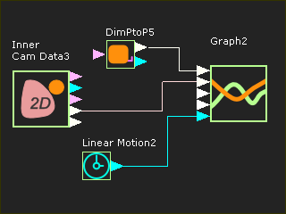
STEP 5: Connect wires from the Cam-Data FB to the Graph FB (see image above)
1.Mechanism-Editor: Connect a wire from the Pressure-Angle output-connector(4) of the Cam-Data FB to the Y2 input-connector of the Graph FB. |
|
|
|
STEP 6: Open the Graph-Settings dialog

|
1.Click : |
STEP 7: Edit the Minimum and Maximum Scales for each Plot.
1.Graph-Settings > Title and Input Selection > Y1 : Dis 
2.Graph-Settings > Y-axis : Disable Auto-scale 
3.Graph-Settings > Y-axis : Y maximum = 150 ; Y minimum = 0
Set the Maximum and Minimum Pressure-Angle
4.Graph-Settings > Title and Input Selection > Y2 : Pressure-Angle
5.Graph-Settings > Y-axis : Disable Auto-scale
6.Graph-Settings > Y-axis : Y maximum = 60 ; Y minimum = -60 (edit again to ±40 as the Pressure Angle improves)
7.Close the Graph-Settings dialog.
Save your model
|
 Graph Settings: Limits of Measurement  Graph FB with Limits for Measurement
Note:
I would normally set the maximum and minimum Pressure-Angle (Y-axis) values to ±35.
However, the Pressure-Angle has a large negative value. Hence, we can set a large range, and reduce the range of the Y-axis as the Pressure-Angle improves.
|