Step 7.2: Add Dimensions to the Design-Set

<< Click to Display Table of Contents >>

Navigation:  Getting Started Tutorials - MechDesigner > Tutorial 7: Design-Sets >

Step 7.2: Add Dimensions to the Design-Set

Important:

After you add a dimension or a parameter to a Design-Set, you can only edit it with the Design-Set dialog.

To edit a dimension or a parameter in the normal way again, you must delete it from the Design-Set dialog.


Open the Design-Set dialog

1.Mechanism-Editor: Double-click the Design-Set

or

See How to open an element's dialog

RESULT

The Design-Set dialog opens.

The Deign-Set dialog is locked.

Design-Set - LOCKED

Design-Set dialog - LOCKED

Unlock the Design-Set

Design-Set dialog - UNLOCKED

Design-Set dialog - UNLOCKED


GST-7-2-DesignSet-LockALL-button-color

1.Click Design-Set toolbar > Padlock

The icons become colorized.

Add Element-Rows

GST-7-2-Design-Set-4Rows-A

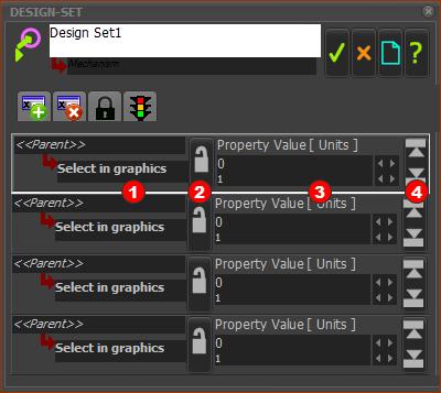
Add four(4) Element-Rows to the Design-Set

GST-7-2-DesignSet-AddElementRow button-color

1. Click Design-Set toolbar > Add Element-Row

2.Do 1 again × 4

There are now 4 Element Rows in the Design-Set.

An Element Row before you select a Dimension or Parameter.

Red-14-1b Select in Graphics - the Element-name (and Parent) that does not have a link to a Dimension or Parameter.

Red-14-2 Padlock - in gray before you select an element - we explain its use later

Red-14-3 Property Value (units) - the value and units of the Dimension or Parameter you select.

Red-14-4 Min-Max button - to limit the element's value between a Minimum and Maximum

The active Element-Row has a white-border around the Element-Row.

Select Dimensions and/or Parameters

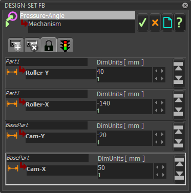
Add to the Design-Set those dimensions that define the position of the Cam-Shaft and the Follower

Do not close the Design-Set dialog


1.Edit the Base-Part.

In the Design-Set dialog:

2.Click an Element Row with the text Select in graphics to make it the active Element Row

3.Click the dimension Red-14-1 that controls the center of the Cam-Shaft from the Y-axis of the Base-Part

4.Click the dimension Red-14-2 that controls the center of the Cam-Shaft from the X-axis  of the Base-Part


Result

Two dimensions are in the Design-Set.

The dimensions are Gray in the graphic-area.

You cannot edit the Dimensions in the Part-Editor.

Dimensions Gray in Part-Editor

X,Y Coordinates of Cam-Shaft in Base-Part

5.Close the Part-Editor (do not close the Design-Set dialog)

6.Edit the Follower Part

In the Design-Set dialog:

7.Click an Element Row with the text Select in graphics to make it the active Element Row

8.Click the dimensionsRed-14-3 that define the center of the Follower-Roller relative to the Y-axis of the Follower Part.

9.Click the dimensionsRed-14-4 that define the center of the Follower-Roller relative to the X-axis of the Follower Part.

10.Close the Part-Editor

11.Close the Deign-Set dialog

Result

There are four dimensions in the Design-Set

The dimensions are Gray in the graphic-area to indicate to you that you cannot edit them with the Part-Editor.

X,Y Coordiantes of Follower-Roller in Follower

X,Y Coordiantes of Follower-Roller in Follower


Dimension or Parameter in the Design-Set

One Element-Row with a Dimension in the Design-Set dialog

Example Element-Row with a Dimension in the Design-Set dialog

Red-14-1b Dimension Name

Red-14-2  Padlock Locked

Red-14-3 DimUnits (mm)

Red-14-4 Min-Max button

Rename the Dimensions

Rename four Dimensions

1.Edit the Base-Part

2.Click Dimension Red-14-1b

It should now be in the Selection-Window

3.Right-click the dimension in the Selection-Window.

4.Click Rename in shortcut-menu

5.Enter Cam-X press ENTER on your keyboard,

6.Close the Rename dialog

7.Do 2-6 again for Dimension Red-14-2 to rename to Cam-Y

8.Exit the Part-Editor

Do 1-8 again to rename the Dimensions Red-14-3 and Red-14-4 that control the position of the Roller in the Follower.

Rename the Dimensions to Roller-X and Roller-Y.


Result

GST-7-204

Save your model