What are Part-Outlines?
A Part-Outline is the symbol for a Part. You can change the size of symbols in the Edit menu > Application Settings | Accessibility tab > Graphs > Symbol Display Size. You cannot edit a Part-Outline. You select the Part-Outline to edit a Part. E.g. •Double-click a Part-Outline to edit the Part in the Part-Editor. •The color of the Part-Outline helps you identify if the Part is or is not, kinematically-defined. |
Why do Part-Outlines have different colors?
You can edit the colors of the Parts that are kinematically-defined and not kinematically-defined. In the Application Settings, we use the terms for the colors of these elements: •Part Solved for a Part that is kinematically-defined •Part Not Solved for a Part that is not kinematically-defined See Edit menu > Application-Settings > Graphic tab > Display Colors > Part Solved / Part Not Solved. |
|
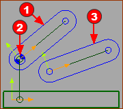
 Free (1) / Completely-Free(3) |
Blue Part-Outlines - or near to Blue. The Part is NOT kinematically-defined. Other names for Blue Parts are: •Completely-Free •Free •Part Not Solved |
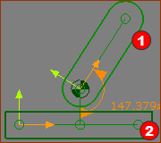
 2 Parts kinematically-defined |
Green Part-Outlines - or near to Green The Part is kinematically-defined. Other names for Green Parts are: •kinematically-defined •Part Solved Note: The Base-Part is always a Part that is kinematically-defined, and therefore near to Green. |
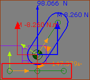
 Part-Outlines : Forces Vectors |
Multi-colored Part-Outlines Each Part has a random color when, in the Forces Toolbar, you: and The color of the Part-Outline is the same as the color of the Force-Vector that acts-on the Part. |