Piggyback-Slider Set 2
Why do we need another set of Piggyback Sliders?
We will add a tool to a chain-link. Each chain-link has two Pin-Joints. The Pin-Joints move along the path of the chain. One Pin-Joint moves ahead of the other.
Our plan is to use two sets of Piggyback-Sliders. Each set moves along the same chain-path, but one set moves ahead of the other. A Point on each set locates a Pin-Joint on the chain-link.
In this Step, we add the second set of Piggyback Sliders.
The second set move ahead of the first set by 30º of the Master Machine Angle.
They are ahead by 30º because there are 12 tools and 360/12 = 30º.
|
When we add the second set of Piggyback Sliders, we can:
•Use again the horizontal Line in the Base-Part for Slider-X2.
•Use again the X-axis and Y-axis motions for Slider-X2 and Slider-Y2
Add Piggyback Sliders - Slider Set 2
Add the new Sliders:
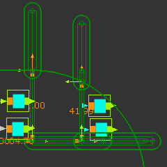
 Two Sets of Piggyback Slider |
1.Add a sliding-Part to the same Line used by Slider-X
2.Edit the new sliding-Part, add a vertical Line. Close the Part-Editor
3.Add a sliding-Part to the vertical Line
4.Add a Motion-Dimension FB to the sliding-Part that moves along the horizontal Line - rename it to Slider-X2
5.Add a Motion-Dimension FB to the sliding-Part that moves along the vertical Line - rename it to Slider-Y2
6.Edit the Base-Values of each new Motion-Dimension FB to equal the Base-Values of Slider-X and Slider-Y |
|
Add the Function-Blocks
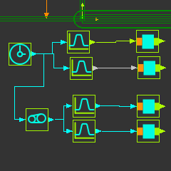
 Function-Blocks for Piggyback Sliders |
1.Add a Motion FB. Edit it to open the Motion FB dialog, select the X-axis motion.
2.Add a Motion FB: Edit it. In the Motion FB dialog, select the Y-axis motion.
3.Rename the Motion FBs correspondingly to X2 and Y2
4.Add a Gearing FB. Edit it. In the Gearing FB dialog: edit
5.Connect the existing Linear-Motion FB to the Gearing FB
6.Connect the Gearing FB to the two Motion FBs (X2, and Y2)
7.Connect the Motion FB with the name X2 to the Motion-Dimension FB that controls Slider-X2
8.Connect the Motion FB with the name Y2 to the Motion-Dimension FB that controls Slider-Y2 |
When you cycle the mechanism, Slider-X2/Y2 lead Sliders-X/Y by 30º of the MMA.
|

