Step 15.4: Add a Chain-Link and Sprockets

<< Click to Display Table of Contents >>

Navigation:  Getting Started Tutorials - MechDesigner > Tutorial 15: Patterns - Indexing-Chain example >

Step 15.4: Add a Chain-Link and Sprockets

A Chain-Link

A Chain-Link moves along the path of the chain. The chain-link rotates as it moves around the arcs of each sprocket.

You will represent a Chain-Link with one of the two Parts in an R-P-R dyad.

The Sprockets

Note: We wrote this topic before the Add Pulley tool became available.

We add one rotating-Part to represent each Sprocket. Their centers are at the center of the arcs of the chain-path.

The sprockets - with 5 teeth - must rotate 12/5 times each time the chain cycles one time.

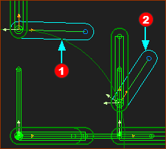
Add an R-P-R dyad to the Slider Sets

Remember, dyads always have two Parts and three Joints.

Add an R-P-R dyad between Slider-Set 1 and Slider-Set 2

This dyad is: R(Pin-Joint) - P(Slide-Joint) - R(Pin-Joint)

Top-Tip: Temporarily hide the Motion-Dimension FBs. See Display Filters: Hide Dimensions

GST-15-401-2xParts-R-R

STEP 1: Add two Parts and two Pin-Joints

1.Add PartRed-14-1

2.Rename PartRed-14-1 to Tool-Part.

3.Add a Pin-Joint between PartRed-14-1 and the start-Point of Slider-Y

4.Add PartRed-14-2

5.Add a Pin-Joint between the PartRed-14-2 and the start-Point of Slider-Y2

Pin-Joints are revolute joints. The Pin-Joints are the revolute joints (R) in the R–P–R dyad.


STEP 2: Add a Slide-Joint

1.Add a Slide-Joint between the CAD-LineRed-14-3 in PartRed-14-1 (Tool-Part) and the CAD-LineRed-14-4 in PartRed-14-2

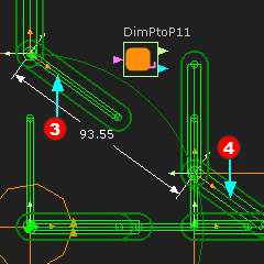
The Slide-Joint is the Prismatic-Joint in the R-P-R dyad.

PartRed-14-1 and PartRed-14-2 are now kinematically-defined.

When you cycle the model, you will see the R-P-R dyad move with the Slider-Sets.


STEP 3: Add a Measurement FB between the Pin-Joints

1.Kinematic FB toolbar > Add Measurement FB

2.Selection Filters toolbar/menu > Enable Filter for Points.

3.Click the Point at the Pin-Joint at R-P-R

4.Click the Point at the Pin-Joint at R-P-R

5.Click the graphic-area to place the dimension

6.Selection Filters toolbar/menu > Disable Filter for Points.

As you cycle the model you will see the dimension vary between 100mm an 93.55mm.

GST-15-402-2xParts-RPR-dyad

Add the Sprockets

A Line for the Pulley on the Left.

A Line for the Pulley on the Left.

The Part for the Pulley on the Left

The Part for the Pulley on the Left

STEP 1: Add rotating-Parts for the sprockets

The start-Point of the Line in the Base-Part that has been used for Slider-X (see Add Slider-X ) can be used for the sprocket on the right.

We must add a Line for the sprocket on the left.

1.Edit the Base-Part: Add a Line: Add Horizontal constraint to the Line, Add Horizontal constraint to the start-Point of the Line and the center of the other Line to locate the center of the two sprockets.

2.Add a Dimension = 350mm to locate the center of the sprocket on the left.

3. Add between start-Point and the center-Point of the left Arc

4.Exit the Part-Editor

5.Mechanism-Editor : Add Pin-Joint , click the start-Point of each Part and the center-Point of each Arcs.


STEP 2: Rotate the sprockets at the correct speed

Make a decision. For each machine-cycle, do you want:

the sprockets to rotate an integer number of times?, Or

the chain to cycle an integer number of chain-lengths?

In this case we will move the chain one length in a machine-cycle. Each sprocket has 5 Teeth.

We can use the Gearing FB to change the rotational speed of the sprockets.  The ratio is –12/5 sprocket rotations for each 1 chain length of 12 Tool-Parts.

The ratio is negative as the sprockets rotate clockwise.

1.Add a Motion-Dimension FB to each rotating-Part - rename them to Sprocket-A and Sprocket-B

2.Add a Gearing FB

3.Edit the Gearing FB : Enter Gearing Ratio = –12/5 (2.4)

4.Add a Linear-Motion FB

5.Add wires between the Function-Blocks in the usual way.

6.Edit Sprocket-A: Base-Value = 0

7.Edit Sprocket-B : Base-Value = 36.

Function-Blocks to rotate the Left and Right Pulleys at the correct speed.

Function-Blocks to rotate the Left and Right Pulleys at the correct speed.