Piggyback Sliders
What is a Piggyback? Is it only an English term? When a person is off the ground and on the back of a standing person, their hands of the person off the ground are around the standing person's neck (to hold, not to strangle!), and their legs around each side and held by the standing person's arms, then the person that is off the ground is being given a Piggyback. We can imagine in a circus act, that the person on the back can also climb up and down a ladder (that is also held by the person on the ground)! The motion of the person on the ladder is a combination of their own motion and the motion of the person on the ground. Why Piggyback Sliders? We can replace each person with a Slider. We can design a different motion for each Slider, say in the X-and Y directions, to give an X-Y planar motion. Why not Piggyback Rockers? Yes, you can add Piggyback Rockers - exactly like a SCARA robot. However, it is almost impossible to predict the planar motion of the Point at the end of a SCARA robot when you design the motion for each Rocker. You will see that, even for a SCARA robot, we design the motion with Piggyback Sliders. We join the tip of the SCARA robot to the Piggyback Slider. |
Piggyback Sliders and a Chain.
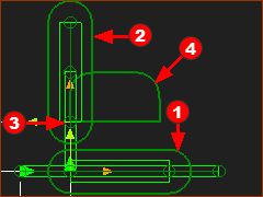
We add two Motion-Parts - Sliders - and assemble them as Piggyback Sliders. We name the Sliders : Slider-X and Slider-Y We design motions for Slider-X and Slider-Y such that a Point on Slider-Y follows the path of a Point on a chain. The motions for Slider-X and Slider-Y are designed here. |
How to add Piggyback Sliders
Basic Instructions: Add Piggyback Sliders
 |
Basic Instructions:
|
Detailed Instructions: Add Piggyback Sliders
 |
Add the Slider-X
|
|
 |
Edit the Slider-X, Add a Vertical Line
|
|
 |
Add the Slider-Y
|
|
 |
Get Motions for the Sliders - Example Motions
|
|
 |
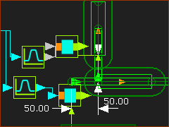
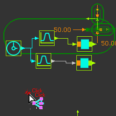
Run menu > Cycle (or ALT+C) Example Motion - not the motion for the chain X Motion - A motion for the X-axis. Use a Motion FB to link this motion to the Motion-Dimension FB to control the motion of the Slider-X. |
|
 |
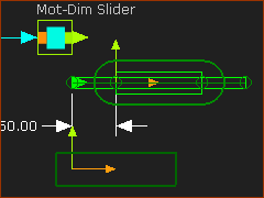
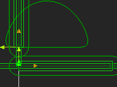
Y Motion A different motion for the Y-axis. Use a different Motion FB to link to the Motion-Dimension FB to control the motion of the Slider-Y. These two example motions define the motion on the Mechanism-Plane To show how the X and Y motions combine we can add a Trace-Point to the Slider that controls the Y-axis motion. |
Design the Motion of the Chain.
We need to design the motions for a point that follows the path of a chain that moves around two sprockets
The motion of the Point is an oval shape. The oval has two equal arcs and two straight line segments between the arcs.
This tutorial does not consider the polygonal/chordal action of a chain as it moves around the sprockets.
Design decisions for the chain, that we have made for you:
•The chain has twelve (12) chain-links
•Each chain-link has a pitch of 100mm
•Each sprocket has five teeth
From these parameters, we can also calculate:
oThe length of the chain is exactly 12 × 100mm = 1200mm
oPitch-Circle Circumference of each sprocket = 5 × 100 = 500mm
oPitch-Circle Radius of each sprocket = 500/2π = 79.577mm
oDistance between sprockets = (1200 – 500) / 2 = 350mm
Background Information: How to model the motion of a chain and sprocket We will use Piggyback Sliders to move a Point along the path of the chain. The sprockets have equal diameters and their shafts are horizontal to each other. The sprockets rotate clockwise. For the motion-design, we will do four steps: STEP 1: Calculate the number-of-segments for the motion. STEP 2: Calculate the Segment-Width of each Segment STEP 3: Define the Motion-Law of each Segment STEP 4: Define the Segment Parameters of each Segment. We must do Steps 1-4 for the horizontal and vertical motions of the Piggyback-Sliders. We will name Sliders: Slider-X and Slider-Y. |
|||
 Schematic - Belt and two Pulleys |
STEP 1: Number-of-Segments The number-of-segments is equal to the number of arcs plus the number of straight sections of the chain's path. There are four Segments - 2 × Arcs + 2 × Straight Sections - see The Number-of-Segments is the same for Slider-X and Slider-Y |
||
 2x Sinusoid, 2x Constant-Velocity Segments |
STEP 2:Segment-Width The chain moves at constant velocity. The motion-width of the all four segments is 360º (Later in Tutorial 15, we will index the belt, also). The Segment-Width of a segment is proportional to the length of the chain along that segment. Segment Width = (Linear Dimensional Length of Segment / Total length of Chain)×360. Remember: the chain has 12 chain-links, the pitch of a chain-link is 100mm, each sprocket has 5 teeth. Therefore: The circumferential length of the chain around half of each sprocket is 250mm Segment-Width of Segment The linear length of the chain between each sprocket is 350mm Segment Width of Segment |
||
STEP 3:Motion-Law of each Segment
STEP 4:Segment Parameters Segments The Sinusoid Motion-Law has three parameters: Amplitude, Phase, and Number-of-Cycles.
|
|||
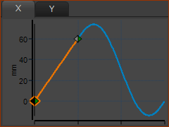
 Sinuoid Motion-Law - Segment-Parameters: X-axis motion |
|||
Segments We calculate for you the Position, Velocity, Acceleration, and Jerk motion-values for the Sinusoid segments. In the Blend-Point Editor (or Segment Editor) select the Match Control-Buttons for each Blend-Point in the motion. The Constant-Velocity segments will automatically match the motion-values at the end of the Sinusoid segments. If the Segment-Width of the Sinusoid and Constant-Velocity segments are correct, the Position at the end of the Constant-Velocity segment will also be correct. Top-Tip: To Design the chain's motion for the Y-axis after the X-axis (or X-axis after the Y-axis)
|
|||
We have entered the Amplitude and the Number-of-Cycles parameters. We need to enter the Phase parameter of the four Sinusoid segments. 1.X-axis motion, Segment 2.Y-axis motion, Segment 3.X-axis motion, Segment 4.Y-axis motion, Segment To find the phase for each, it is best to draw a sketch to visualize the horizontal-only motion (X-axis) and vertical-only (Y-axis) motions for a point as it enters and exits each sprocket. |
|||
Segment |
|||
 Schematic of Right-Hand Pulley |
X-axis motion-values - horizontal-only
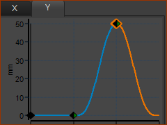
Y-axis motion-values - vertical-only
|
||
 Phase of Sinusoid Segment 1- X-axis |
X-axis Segment
|
||
 Phase of Sinusoid Segment 1 - Y-axis |
Y-axis Segment
|
||
Segment |
|||
 Svhematic of Left-Hand Pulley |
X Values - horizontal-only
Y Values - vertical-only
|
||
 Phase of Sinusoid Segment 3- X-axis |
X-axis Segment
|
||
 Phase of Sinusoid Segment 3- Y-axis |
Y-axis Segment
|
||
 |
The Trace-Point is the path of the chain. |