How to prepare and import SOLIDWORKS Parts and Assemblies
Use the CAD-Line dialog | SolidWorks tab to import SOLIDWORKS Part and Assembly documents.
Notes:
SOLIDWORKS® is a registered name, and owned by Dassault Systèmes.
“document” is the generic term that we use for a model in SOLIDWORKS®: e.g.: Part document, Assembly document.
From MD14+, we automatically check for you the SOLIDWORKS® release that you have used most recently, and change MechDesigner to use the correct Type-Library. You can also check that the Type-Library is correct: see Help menu > About > Type-Library tab. |
Coordinate System in MechDesigner
 Standard CAD-Line (2) Add CAD-Line with the Part-Editor") (1) Standard CAD-Line |
CAD-Lines:
Each CAD-Line has a Coordinate-System:
|
Coordinate System in SOLIDWORKS
Usually, you add a Coordinate System feature to the SOLIDWORKS document to align it with the Coordinate-System of a CAD-Line in MechDesigner. |
|||
 SOLIDWORKS CAD model prepared for import to MechDesigner |
In SOLIDWORKS, to add a Coordinate System, you must select a Point or Vertex, and a Line or Edge. Rather than select from the model's existing features, I usually do these steps in SOLIDWORKS: SOLIDWORKS to add a Coordinate System
|
||
 Add Coordinate Syastem dialog in SOLIDWORKS |
|
||
To Import SOLIDWORKS Documents:
SOLIDWORKS: Add a Coordinate System to the SOLIDWORKS document. See above : To add a Coordinate System in SOLIDWORKS MechDesigner: Make sure there is an active document open in SolidWorks® As a minimum, you must do: STEP 1: Click the Read STEP 2: Click the Import The other buttons are optional. Enable Visibility toolbar > Show Solids in Mechanism to see the SOLIDWORKS document. |
||
 CAD-Line dialog > SOLIDWORKS tab |
STEP 1: Click the Button WAIT until the •SolidWorks® Part/Assembly (read-only) is in box •SolidWorks Configuration (read-only) is in box •Current Model Status (read-only) is in box
If there is more than one Coordinate system in the SOLIDWORKS document: •Select the SolidWorks Coordinate-System STEP 2: Click the Button Wait - a large model can take time to import. Optional Buttons ( Button Button Button |
|
Notes on CAD-Solid File Quality
|
||
If the sub-assembly has many parts and features that you do not need to see in the MechDesigner model - for example washers, screws... - then in SOLIDWORKS, create a new Configuration. In the new SOLIDWORKS configuration, suppress parts and features that you do not need to see. Also, suppress fillets, or replace with chamfers, where possible. SOLIDWORKS: 1.Make active the configuration in which you have suppressed parts and features. 2.Add a Plane and Coordinate System, ... - see Method 1: above MechDesigner See Method 1 above |
To import more than one SOLIDWORKS document onto one MechDesigner Part, you must use the Psrt-Editor to add to it more CAD-Lines. PREPARATION SOLIDWORKS: 1.At the top level of the assembly: add a Plane. We might call this the Master Plane. Drag it to the top of the Assembly Feature-Manager, if possible. In the assembly, Edit Parts in Context - that is, do not leave the SolidWorks assembly to edit each part. 2.Edit Part A in Context: a.Add a Plane, and make it coplanar with the Master Plane b.Add a sketch to the new Plane, and then add the Coordinate System. c. Close Edit Part in Context 3.Do 2 for each Part in the Assembly - ALL COORDINATE SYSTEMS SHOULD BE COINCIDENT. MechDesigner: 4.Edit a Part and add CAD-Lines equal to the number of documents/parts you will import from SOLIDWORKS onto the one Part. 5.Make the start-Point of all of the new CAD-Lines coincident with the origin of the Part, and make each CAD-Line collinear with X-axis. IMPORT EACH PART: SOLIDWORKS: 1.Open a SOLIDWORKS Part. The Plane, sketch and Coordinate-System should be a feature in the Part. The Part is now the active document in SOLIDWORKS. MechDesigner: 2.Edit each CAD-Line: and import the SOLIDWORKS Part. 3.Rename each CAD-Line to the same as each SOLIDWORKS Part. Do 1-3 for each SOLIDWORKS Part you want to import. |
All of the XY-Planes in each Coordinate-System should be coplanar. Their Origins and X-axes do not need to be coincident, of course, as they will be imported on to different MechDesigner Parts. Again, we use a Master-Plane in the SOLIDWORKS document. In SOLIDWORKS 1.At the top level of the assembly, add a Plane. We can call it the Master Plane. Move it to the top of the Assembly Feature-Manager, if possible. In the assembly 2.Edit Part A in Context: that is, do not leave the SolidWorks assembly to edit the Part. a.Add a Plane, and make it coplanar with the Master Plane Do 2 for each SOLIDWORKS part you want to import to MechDesigner. 3.Open each Part a.Add a sketch to the Plane in each Part, and then a Coordinate System. b.Make sure each Coordinate System will align with the CAD-Line in each MechDesigner Part. Do 3 for each part you want to import. In MechDesigner: 1.Make sure the correct document is the active document in SOLIDWORKS. 2.Edit a CAD-Line; and import the SOLIDWORKS Part. 3.Rename the CAD-Line to the SOLIDWORKS Part. Do 1-3 with each CAD-Line and SOLIDWORKS Part. |
When do you need to import STL file-types? •When you do not have SOLIDWORKS. •You can save a model as the STL file-type in your CAD software. Notes: in your CAD software: •Save as a STL file in the Binary Format •The STL file-type does not use a Coordinate System. Thus, before you save the STL file: oMove the original CAD part so that its Front-View is the same as the Front-View of the Mechanism-Editor. Note: It is possible to move the STL part in the X, Y, Z-axis directions, but not rotate the model - see below |
|
 |
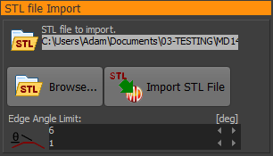
To import an STL file onto the CAD-Line: CAD-Line dialog > STL Import tab > STL file import separator: 1.Click the Browse button 2.Select an STL file (Binary) 3.Click the Import STL File Button: Look at the model in MechDesigner. |
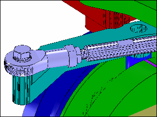
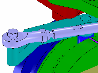
Edge Angle Limit parameter and STL files. We use the Edge Angle Limit parameter to remove 'ghost edges' from facets in the STL file. If the angle between a facet in the STL file is less than the Edge Angle Limit parameter, then we do not show an 'edge'. The Edge-Angle-Limit parameter value is a function of the Linear Deviation and Angular Deviation parameters in the 'Model Import from SOLIDWORKS' separator. To the left, compare the top image with the bottom image. |
|
 |
|
The STL file tessellates the surfaces of the CAD model as a mesh of triangles. Each triangle can appear as a small face - a facet. The number of facets is a function of: •the complexity of the original CAD model, and •how accurately you want the STL file to tessellate the original CAD model. To build complex models, and import many STL files, you want a: •Small STL file-size •AND it to appear as the original CAD model •AND not to see the facets Strategies to reduce the STL file-size. Strategy 1: Reduce the complexity of the original CAD Model = SMALL file-size Add a new configuration for the CAD model. In the new configuration: •Do a geometry check of the CAD model file to find if it has small gaps or whiskers. •Suspend small fillets, especially if they do not have a function. •Replace fillets with chamfers, especially along straight edges. •Suspend all fasteners •Suspend fastener holes and hole features. •Suspend all cosmetic details. |
||
Strategy 2: Reduce the accuracy of the STL file There are two parameters to control the accuracy of the STL file: If you do not have SolidWorks, you must find these parameters in your CAD before you save the STL file. It is possible they are options in the Save as > STL file-type. You are looking for two parameters: |
||
Linear Deviation : |
The allowable chordal deviation (distance) between the surface of the original CAD model and the tessellated surface of the STL file. SolidWorks tab | Import from SolidWorks : Linear Deviation - Minimum=0.014mm ; Maximum=0.5mm |
|
Angular Deviation : |
The allowable angular deviation between adjacent facets of the tessellated surface of the STL file. See SolidWorks tab | Import from SolidWorks Angular Deviation - Minimum=0.4º ; Maximum=30º |
|
Strategy 3: Use the Edge Angle Limit parameter - see STL File Import aboveSmall STL files may show their facets. You can improve how the facets display with my Magic Number! Edge Angle Limit = Angular Deviation × Π ÷2 |
||
 STL tessellation: Many Vertices |
|
|
BAD Example - too many facets •Linear Deviation = 0.014 and •Angular Deviation = 0.4º There are •119132 vertices •~40000 triangles •The STL file size is 3.5 Mega Bytes!!! |
||
 STL tessellation: Not many Verticies |
||
GOOD Example - not many facets •Linear Deviation = 0..5mm and •Angular Deviation = 5º There are: •7533 vertices •2500 triangles •The STL file size is 0.365 Mega Bytes The CAD models in the graphics-area are similar. |
||