A Rocker and a Spring
In this topic, you balance the force that acts on the Rocker with a Spring.
You balance the
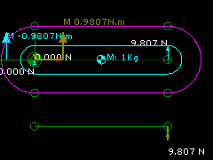
•Downward Force and Clockwise Moment on the Rocker that result from Gravitational Force
with ...
•an Upward Force and Counter-Clockwise Moment on the Rocker from a Spring FB
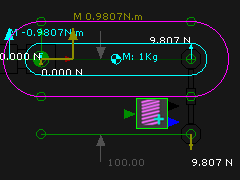
A Spring FB exerts a force between Points (called anchor-points) that are in two different Parts. In this case, we need an anchor-Point in the Rocker and an anchor-point in the Base-Part. The Rocker is stationary.
|
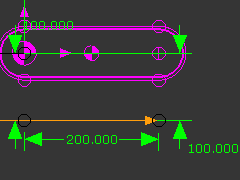
STEP 1: Edit the Base-Part to add a Line
TOP-TIP: You can use Tools menu > Show other Kinematic and Sketch-Elements to see the Rocker when you edit other Parts in the Part-Editor. |
||
|
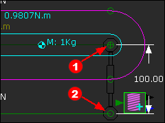
STEP 2: Add a Spring FB To add the Spring FB you must click a Point in two different Parts
The Points become the Anchor-Points for the Spring FB. |
||
|
|||
|
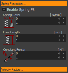
STEP 3: Enable the Spring FB
|
||
|
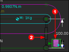
The image to the left shows the Spring FB The Spring FB does not exert a Force, yet. Thus, Force Vectors are not at the Spring's anchor-points. Constant Force
STEP 4: Edit the Spring FB to enter a Constant-Force= –9.80665N
–9.80665N exerts a Force upwards against the Rocker. |
||
 -9.8066N |
|||
|
Add the Vertical Forces acting on the Rocker (upwards +ve).
Add the Horizontal Forces acting on the Rocker (Point 2) : (upwards +ve).
R2H(N) = 0; R2H = 0N Take Moments about Z-axis at the Rotational Center of the Rocker (Counter-clockwise +ve)
M2 + 0.2(m)*9.81(N) - 0.1(m)*9.81(N) = 0 . Thus M2= -0.981Nm. |
||
|
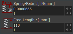
Spring-Rate and Free-Length You can use the Spring-Rate and Free-Length parameters to give you the same result. We will enter a Free-Length and Spring-Rate so that the Spring exerts a force equal and opposite to the Gravitational Force. Also, edit the Constant Force = 0N again. |
||
|
When we make the Free-Length = 110mm and the Spring-Rate = 0.980665N/mm, the Spring FB will exert 9.80665N upwards. Why? The model controls the actual distance between the anchor-points of the Spring FB - the actual distance is 100mm. Therefore, the model deflects the Spring by 10mm Therefore, the Spring FB exerts a Force = 10mm * 0.98066N/mm = 9.81N upwards |
||
Note: The Spring FB has: Two output-connectors : •Top output-connector = Distance, velocity and acceleration of one anchor-point relative to the other. •Bottom output-connector =Total Force, X-Force and Y-Force (relative to the coordinate axes of the Mechanism-Plane). One input Connector : Optionally, a Force Function at its input-connector from a Math FB. The Output Data-Type of the Math FB must be set to Force. |
|||
