SLIDER FORCES
This topic uses the Force Vectors: Calculate and Force Vectors : Display tools with a Slider.
•Slider = Part + Slide-Joint + Motion-Dimension FB.
Note:
Motions for this Step: Motions for Tutorial13-1B Download the ZIP file, extract the MTD.
Use MotionDesigner > Open and Append to load the motions into MotionDesigner.
The Slider
 Position of a Line in a Part |
The top image shows the Slider open in the Part-Editor.
The next image shows the Slider in the Mechanism-Editor
Mass of the Slider
|
||||
 4x Point in a Slide-Joint |
|||||
 Schematic- Linear Slide-Block and Slide-Rail. |
Note: This is a schematic of a typical Linear Slider Rail with a Slide Block that you might use in a machine design. 1, 2, 3, and 4 - in the image - are approximately equivalent to the start-Points and end-Points of the two Lines in a Slide-Joint. In your model you should make sure Lines in the Slide-Joint are approximately equal to the length of the Slide-Rail and Slide-Block in your machine. Then, the reaction forces will be correct. |
||||
Calculate and Display Forces
|
1.Enable Force toolbar > Force Vectors : Calculate - the icon is the same as the icon to the left. |
|
|
2.Enable Force toolbar > Force Vectors : Display - the icon is the same as the icon to the left. |
|
If a minimum of one Part has Mass, we display for you the Force Vectors. The Force Vectors show the direction, magnitude, and location of each Force. Note: Click the Force and Torque Vector Scale buttons to increase or decrease the length of the Force Vectors. The buttons are below the graphics-area, in the middle of the Feedback Area.
|
||
CASE 1: Stationary or Constant Velocity Slider
When the Slider moves along the Slide-Joint at Constant-Velocity, the Inertia-Forces are zero. Also, as the Slider is not rotating, the Coriolis-Force and Centrifugal-Force are zero. |
|||
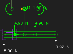 |
Consider the Forces that act on the Sliding-Part. •Gravitational-Force: The Slider has a Mass of 1kg. Thus, there is a Gravitational Force = 9.81N. This force vector is not shown. •Inertia-Force: It is stationary (or moving at a constant-velocity). Thus, the Inertia Force = 0N The Gravitational Force must be put into equilibrium by reaction forces that act on the Slider. There are two force-vectors that act upwards that are equal to 4.90N. They ACT ON the Slider. These two Force Vectors are equal because the mass is above the mid-Point of the Slider, and the Slide-Joint is horizontal. |
||
Consider the Forces that act on the Base-Part. Refer to the dimensions and point numbers in the image at the top of this topic. The total force acting on the Slider (by the Base-Part) is = 9.81N. Summation of Moments, about Point
Summation of Vertical Forces:
These Force Vectors ACT ON the Base-Part, from of the mass of the Slider and its Gravitational Force. |
|||
The Force Vectors on the Base-Part as the Slider moves along it with Constant-Velocity. The forces would be uniformly distributed along the Lines in the two Parts. However, in MechDesigner, the Forces Vectors are at the start-Points and end-Points at the ends Lines in the Slide-Joint. |
|||
Slider Forces - with Constant-Velocity
|
|||

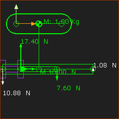
CASE 2: Accelerating Slider.
Note: Edit menu > Machine Settings > Cycling Parameters > Cycles/Min to 300. Link the Motion FB to the ConstAcc motion. The acceleration of the Slider is 10m/s/s. |
|||||
|
Consider the Force Vectors that act on the Sliding-Part.
Summation of Horizontal Forces
These force vectors must be balanced by the reaction force acting on the sliding-part. Summation of Moments Point
Summation of Vertical Forces ( ↑+ve)
|
||||
Consider the Force Vectors that act on the Base-Part. The total force acting upwards by the Base-Part on the Slider is 9.81N. Summation of Moments at Point
Summation of Vertical Forces
These force vectors ACT ON the Base-Part. |
|||||
|
|||||