Add a 2D-Cam and Configure the Power Source
When we add a 2D-Cam, and we want to know the Contact-Force, Maximum Shear-Stress, and Life of the Follower-Roller and/or Cam-Profile, we must also Configure the Power Source.
In this Step 13.4, we will:
1.Delete the Spring FB.
2.Delete the wire between the output-connector of the Linear-Motion FB and the input-connector of the Motion-Dimension FB.
3.Do and to extrude the 2D-Cam as an MD-Solid (Note, not required for Contact-Force).
4.Use Configure the Power Source to move the Power-Source from the Follower's Pin-Joint / rotating-axis to the 2D-Cam. |
Add a Follower-Roller
|
Add a Follower-Roller to the Rocker.
1.Edit the Rocker, Add a Circle (100 Radius), Add Coincident to move its center-Point to the end-Point of the Rocker, Close the Part-Editor.
2.Add a Profile to the Circle.
3.Edit the Density of the Profile/Extrusion until its mass is ~1kg. The Follower Profile:
•Weighs 10N (a mass ~1kg)
•Center-of-mass (the center of the Circle) is 200mm, horizontally, from the Pin-Joint. |
|
|
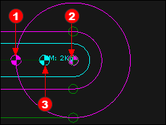
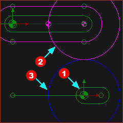
The image is the end of the Rocker.
Note: there are three symbols that identify the:
 Center-of-mass of the original Profile (1kg @100,0) Center-of-mass of the original Profile (1kg @100,0)
 Center-of-mass of the Follower-Roller Profile (1kg @200,0) Center-of-mass of the Follower-Roller Profile (1kg @200,0)
 Center-of-mass of all of the Profiles in the Part / Rocker (2kg, @150mm). It has a color that matches the color of the Part-Outline. Center-of-mass of all of the Profiles in the Part / Rocker (2kg, @150mm). It has a color that matches the color of the Part-Outline.
|
|
|
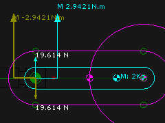
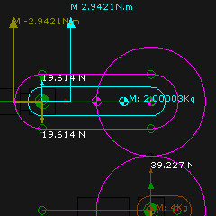
Forces and Moments with a Profile 1kg @ x=100mm, y=0, and a Follower-Roller Profile of 1kg @ x=200mm, y=0
Forces:
∑ Vertical Forces acting on the Rocker (+ is Up)
-(1(kg) + 1(kg))* 9.81(m/s/s) = -19.62N (Down)
∴ Reaction Force from the Base-Part that acts on the Rocker is +19.62N (Up).
|
Moments:
∑ Moments acting on the Rocker (+ is Anti-Clockwise)
-1(kg)*9.81(m/s^2)*0.1(m) - 1(kg)*9.81(m/s^2)*0.2(m) = –2.943Nm (Clockwise Moment)
∴ Reaction Moment from the Base-Part that acts on the Rocker = +2.943Nm (Anti-clockwise).
|
|
Add a Cam-Part and 2D-Cam
|
Disable Force Vectors: Display temporarily, to hide the Force Vectors, while we add a Part for the cam.
STEP 1:Add a Cam-Part
1.Edit the Base-Part, Add a horizontal Line. The end-Point of the Line is at 200,–200 mm
2.Add a Part - the Cam-Part
3.Add a Pin-Joint. Click the start-Point of the Part and the end-Point of the Line.
4.Add a Motion-Dimension FB to control the angle of the Cam-Part
5.Add a Linear-Motion FB to control the rotation of the Cam-Part |
|
|
STEP 1:Add 2D-Cam

|
1.Click > |
a.Click the Cam-Part
b.Click the Follower Profile |
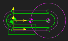
The 2D-Cam is circular because the Follower-Roller does not move.
STEP 2:Hide the Outer Cam
1.Double-click the 2D-Cam in the graphics-area to open the 2D-Cam dialog.
2.Click the Display tab > Cam Profile Display > . |
|
Add Mass to the Cam a Mass
Note: We do not need to add mass the Cam a Mass. However, it is a good opportunity to remind you of how you can, if you really want to, do and . to extrude the 2D-Cam as a Solid.
|
|
STEP 1: Add a Polyline to the 2D-Cam

|
1.Click the Home key on your keyboard
2.Click - see icon to the left
3.Click the 2D-Cam
4.Click  in the Command-Manager in the Command-Manager |
The Polyline is superimpose over the 2D-Cam.
STEP 2: We can add a Profile to a Polyline

|
1.Click - see icon to the left
2.Click the Polyline - it is superimposed over the 2D-Cam
3.Click in the Command-Manager |
|
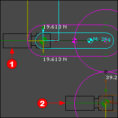
You can see the force and moment that act on the Rocker are the same as before, 19.61N and 2.942Nm, respectively.
The Problem : Where is the Contact Force between the Cam and Follower?
For convenience, the mass of the 2D-Cam equal 4kg . To edit the mass, edit the or of the Extrusion
Therefore, there is a Force that acts on the 2D-Cam of 39.227N.
|
Configure the Power Source
|
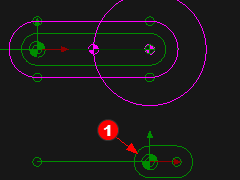
Why is the Contact Force between the Cam and the Cam-Profile equal to zero?
In the image to the left, there are two Power Source (2 Motors)
•Motor drives the Rocker
•Motor drives the Cam-Part
There is usually ONE motor to drive a Cam mechanism! This is because:
•Motor does not exist. The 2D-Cam drives the Follower / Rocker, and not a motor.
•Motor is OK. It drives the Cam-Part. |
We must Configure the Power Source to make the 2D-Cam drive the Follower / Rocker.
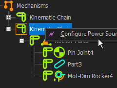
STEP 1: To open the Configure Power Source dialog:
In the Kinematics-Tree, do these three(3) clicks
a)Click the Kinematic-Chain that includes the Follower
b)Right-Click the Kinematic-Chain
c)Click Configure Power Source
or
|

|
a)Click the kinematic-chain with the Follower
b)Click |
|
|
|
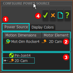
In Configure Power Source dialog is now open.
STEP 2: Select the Power-Source in the Configure Power Source
Click the Power Source tab
Click Mot-Dim Rocker
Mot-Dim Rocker is the Motion-Dimension we want to drive with a Power-Source
The default Power Source is Pin-Joint.
Click the 2D-Cam
2D-Cam is now Power-Source to drive the Motion-Dimension (Mot-Dim Rocker)
The  icon (a small motor) is now to the left of the 2D-Cam to indicate it is the Power-Source. icon (a small motor) is now to the left of the 2D-Cam to indicate it is the Power-Source.
The 2D-Cam is the Motor Element to the right of Mot-Dim Rocker.
 Click to close the dialog Click to close the dialog
|
|
|
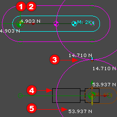
You should see that:
1.The Motor symbol is not at the Pin-Joint of the Follower / Rocker
2.There is not a Torque vector at the Follower Pin-Joint.
3.Action and reaction forces at the Cam Contact
4.The Motor symbol at the Cam-Shaft
5.The Action and Reaction Forces at the center of the 2D-Cam are now 53.94N,
The center of the 2D-Cam must support the weight (m*g) of the Follower/Rocker and the Follower-Roller
The 2D-Cam does not need a torque because it does not do useful work. The 2D-Cam simply supports the mass of the Follower and Follower-Roller.
|
|