Cam Speed and the Follower Contact Force.
The Follower-Part and the Follower-Roller have mass. As you increase the machine speed, the acceleration and inertia forces also increase.
In this step,
1.You move the Follower-Part with a Motion from MotionDesigner.
2.We increase the machine speed until the Contact-Force between the Cam-Profile and Follower-Profile becomes zero or negative.
Add a Motion to the Follower.
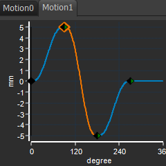 |
The motion will oscillate the Follower-Part by ±5º, a total of angle of 10º. Use the tools in MotionDesigner to design the motion to the left.
|
 |
1.Add a Motion FB to the graphics-area. 2.Edit the Motion FB. In the Select Motion drop-down box, select Motion1. 3.Connect the Linear-Motion FB I have disabled Force Vectors : Display to make it easier to see the shape of the new Cam-Profile. See, in the image: •The new Cam-Profile (Cyan) •The Profile (Pink) |
Cam Contact Force
There are four methods to show the Contact-Force between a Cam-Profile and Follower-Profile Note : With all four methods, you must Configure the Power Source to make sure the 2D-Cam is the Power-Source for the Follower. |
|
 |
Method 1: Force Vectors : Display to show the •Force-Vector that ACTS-ON the Follower-Profile •Force-Vector that ACTS-ON the Cam-Profile YOU must determine whether the contact-force is active ON (towards) the Cam-Profile or active OFF (away from) the Cam-Profile. Method 2: 2D-Cam > Cam Display Options > Contact-Force. Method 3: Force-Data FB and plot with a Graph FB. YOU must determine whether the contact-force is active ON (towards) the 2D-Cam or active OFF (away from) the 2D-Cam. Method 4: Use a Cam-Data FB. connect the Contact Force output to a Graph FB. If the Contact Force ≤ Zero(0), then the Contact-Force is = Zero(0). Method 4 is usually the most informative. |
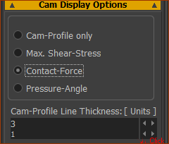 |
We will use Method 2: 2D-Cam dialog. 1.Double-click the 2D-Cam The 2D-Cam dialog opens. We want to show the contact force In the Cam Display Options separator, enable: ◉ Contact Force To see the colors more clearly, enter: Cam Profile Line Thickness: = 2 or 3 |
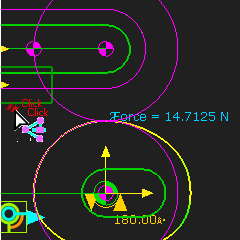 |
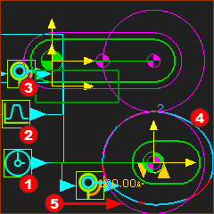
In the graphics-area, the: •Cam-Profile has a color-code •Contact-Force is at the contact point •Color-code swatch and Force Scale at the left of the graphics-area.
|
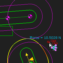 |
Drag the Master-Machine-Angle until the Contact-Force is a minimum. For my motion, the minimum contact-force is when the Master-Machine-Angle is 110º. The minimum contact-force is approximately at the maximum deceleration of the Follower. |
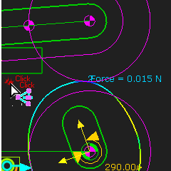 |
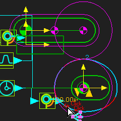
Do Edit menu > Machine Settings dialog Increase the Machine-Speed (Cycles / Min (RPM)) until the Contact-Force is approximately 0N. Again, drag the Master Machine Angle until the Contact-Force is at a minimum. If the contact-force is a function of inertia, gravity, and springs, then the minimum will be at different machine-angles for different machine-speeds. For my motion, the Contact-Force becomes ~0N when the cam-shaft rotates at ~111 Cycles / minute. (RPM) The maximum speed is a function of: •The motion •The mass and mass distribution of the Follower. Are there ways to increase the speed of the cam-shaft, but use the same motion and the same mass distribution? |