<< Click to Display Table of Contents >> Navigation: Getting Started Tutorials - MechDesigner > Tutorial 3: Add a Sketch-Loop to a Part > Step 3.2: Add Lines & Arcs as Sketch-Loop |
•Define a sketch-path and sketch-loop and where it may be used.
•Understand the difference between Merged-Points and Coincident Points
•Add Line and Arc sketch-elements to give a sketch-loop.
Definitions of Sketch-Path and Sketch-Loop
A sketch-Path is a minimum of two sketch-elements, in which the start-Point of second sketch-element is MERGED with end-Point of first sketch-element. You can continue to merge the start-Points of more sketch-elements to extend the sketch-path.
A Sketch-Loop is a Sketch-Path that is also made into a continuous, closed loop, with all end-Points merged
Why add a Sketch-Loop?
Sketch-loop/sketch-path are important constructions in MechDesigner.
We need sketch-paths / sketch-loops for Belt Paths, Chain Paths, Gear Trains, and Extrusion for MD-Solids.
Add 3 Lines and 3 Arcs as sketch-Loop
Note: Coincident-Constraints will not give a sketch-loop. Add two Lines 1.Part-Editor: Click Geometry toolbar > Add Line, Drag in graphic-area. 2.Do Add Line again |
|
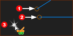
![]() Start-Points or end-Points of Lines in graphic-area |
Do Add Coincident Constraint: 1.Part-Editor: Click Constraints toolbar > Add Coincident Coincident a.Part-Editor: Click the Point b.Part-Editor: Click Point The two Points become coincident. Note: Point *start-Point or end-Point at the end of a Line |
![]() SHIFT+Click the Point to identify constraints in the Selection-Window |
Delete Coincident Constraint We must show the Coincident-Constraint in the Selection-Window 1.Part-Editor: Right-Click to deselect active commands 2.Part-Editor: CLICK the Point with the Coincident Constraint There two Points are in the Selection-Window, But, the Coincident Constraint is NOT in the Selection-Window! |
![]() Contextual menu after Right-Click in the Selection-Window |
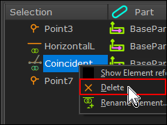
We must: 1.Part-Editor: SHIFT+ CLICK the Point with the Coincident Constraint The two Points and the Coincident Constraint are in the Selection-Window In the Selection-Window: 2.Right-click the Coincident-Constraint 3.Click Delete in the contextual-menu Now, Click and Drag one of the Lines to move them apart again. |
Summary: •Add Coincident does not delete a Point. •You can delete the Coincident-Constraint. |
Note: This is the inefficient technique, that I rarely use. The Hover technique is much faster - see below. If I make a mistake with the Hover technique, I use Merge-Points in the toolbar to repair a sketch-loop. Add two Lines 1.Part-Editor: Click Geometry toolbar > Add Line, Drag in graphic-area. 2.Do Add Line again |
|
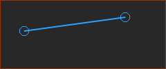
![]() Start-Points or end-Points of Lines in graphic-area |
Do Merge-Points: 1.Part-Editor: Click Geometry toolbar > Merge-Points a.Part-Editor: Click Point b.Part-Editor: Click Point c.Click the graphic-area in a place with no other elements. * start-Point or end-Point at the end of a Line Delete Merge-Points !?! 1.Part-Editor: Right-Click to deselect active commands 2.Part-Editor: SHIFT+CLICK the Points that are Merged Only ONE Point is in the Selection-Window. |
Summary: Merge-Points removes a Point element. You cannot delete the Merge-Points. Merge-Points is not an element. |
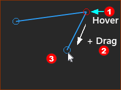
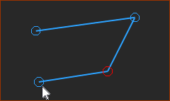
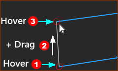
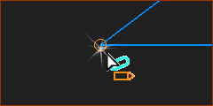
This is the efficient technique. I nearly always use this technique. To add the first sketch-element: 1.Add the first sketch-element with the usual drag technique. To add the second sketch-element: Before you Mouse-Button-Down... 2.Move you mouse-pointer above the end-Point of the first sketch-element so that only the Point becomes red 3.Mouse-button-down... ...move your mouse... ...mouse-button-up. The new sketch-element should now be in the graphic-area. The start-Point of the second sketch-element is Merged with the end-Point of the first sketch-element. To add more sketch-elements. Continue to do 2 and 3 to add more sketch-elements. To add the last sketch-element: Before you Mouse-Button-Down... 1.Move you mouse-pointer above the end-Point of the last sketch-element ... 2.Mouse-button-down... move your mouse... Before you Mouse-Button-Up... 3.Hover above the start-Point of the first sketch-element .... 4.... mouse-button-up A sketch-loop is complete. Should you fail to hover correctly, repair the sketch-loop with Geometry-toolbar > Merge-Point. |
![]() | Add Sketch-Loop of Lines and Arcs with Hover Technique |
To add a sketch-loop, the start-Point of a sketch-elements is Merged with the end-Point of an adjacent sketch-element. |
|
STEP 1: Click Geometry toolbar > Add Line STEP 2: Drag the Line, approximately as in the image to the left
|
|
STEP 3: Click Geometry toolbar > Add Arc To add the Arc you must Drag two times:. For a sketch-loop: we merge the start-Point of the Arc and the end-Point of the Line. Drag 1: Hover and Drag Hover above the end-Point of the Line so it becomes red, + Drag: ... mouse-button down ... move your mouse-pointer ... mouse-button-up. Drag 2: Locate the radius of the Arc Move your mouse-pointer between the start-Point and end-Point of the Arc. Mouse-button down, again and drag to approximate the radius of the Arc |
|
Do Add Line and Add Arc commands again, two more times.
STEP 4: Add two more Lines and two more Arcs. with the Merge Technique When you add the last sketch-element STEP 5: Hover above the end-Point of the next-to-last sketch-element and the start-Point of the first sketch-element, to complete the sketch-loop. |
|
If you miss a Point as you add the sketch-elements, CTRL+Z or use Geometry toolbar > Merge-Points to merge two Points into one Point. The sketch-loop is similar to the image above. |