Objective of this Step
To do the commands in Tutorial 1 again.

|
Add a new ... (a new command)
|

|
... add a new Mechanism-Editor to the new ... (see Tutorial 1)
|

|
... add a new to the new Mechanism-Editor ... (see Tutorial 1)
|

|
... edit the length of the ... edit the to add a ... (see Tutorial 1)
|

|
... add a between a in the and a in the ... add a ... (see Tutorial 1)
|
To add a new in the Model-Editor, you must select a different Plane.
|
|
|
STEP 1: Begin this tutorial in the Model-Editor
1.Click the Model name-tab
2.Click |
The Plane dialog opens.
|
 Add Plane dialog-box |
The default Plane dialog:
 The name of the new Plane at the top of the dialog (Plane6). The name of the new Plane at the top of the dialog (Plane6).
 The default Plane Definition, which is Offset from Plane. The default Plane Definition, which is Offset from Plane.
 The default parameter name is Distance to New Plane. The default value is 100mm. The default parameter name is Distance to New Plane. The default value is 100mm.
 The default Plane element in the Element box is the Front Plane, from which the new Plane (Plane6) is offset. The default Plane element in the Element box is the Front Plane, from which the new Plane (Plane6) is offset.
|
|
 Select a Plane in the graphic-area |
STEP 2: Select the Plane in the Assembly-Tree or the graphics-area.
1.Expand the Model element at the top of the Assembly-Tree
2.Click the Right in the Assembly-Tree in the Assembly-Tree
OR
2.Click a Plane in the graphics-area.
If you select more than one Plane in the graphics-area they all show in the .
In the Selection-Window,
3.Click the Plane you want to select.
Again, make sure the correct Plane (Right in this example) is in the Element box of the Plane dialog in this example) is in the Element box of the Plane dialog
|
STEP 3: Edit the Distance to the New Plane.
1.Use the Spin-box tool at the right of the  parameter box parameter box
or
1.Use your keyboard to enter a new value in the parameter box
2.Press the ENTER key on your keyboard. |
STEP 4: Complete the Command
1.Click  to close the Plane dialog to close the Plane dialog |
|
 RIGHT Plane in Add Plane dialog-box |
 New Plane in graphic-area |
If you spin the view (See , or use your arrow-keys on your keyboard) you can see the new Plane in the graphics-area.
|
 Model toolbar |
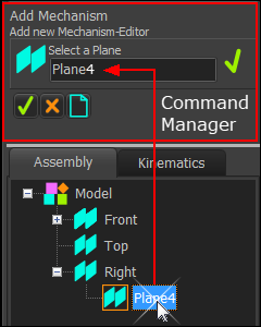
STEP 1: Add a new Mechanism-Editor
The Command-Manager has one selection-box
STEP 2: Select a Plane
1.Click the Plane in the:
•
or
•graphics-area |
is now the element in the selection box in the Command-Manager.
To select a different Plane:
1.Click in the selection-box.
We clear the element from the selection-box.
2.Click a different Plane in the Assembly-Tree or graphics-area. |
|
|
 Mechanism name-tabs
 Assembly-Tree with Mechanism and Base-Part |
STEP 3: Complete the Command
1.Click to close the Command-Manager. |
You immediately jump to the new Mechanism-Editor. There is now a new Mechanism name-tab.
At the top of the graphics-area there are two Mechanism name-tabs.
“Mechanism1” name-tab is to the right of “Mechanism ”name-tab
In the Assembly-Tree
Mechanism1 element is a child to Plane4 element.
To rename a Mechanism:
1.Right-Click the Mechanism element in the
2.Select Rename element in the shortcut-menu
3.Use the Rename dialog to give a new name. |
|
|
STEP 1: Start the Add Part command
|
1.Expand the to the left of the graphics-area.
2.Click
OR
1.Keyboard Shortcut: Click the key on your keyboard |
STEP 2: Add the Part.
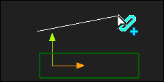
1.Drag in the graphics-area |
When you release you mouse-button, the new Part is in the graphics-area.
In the graphics-area, the Part has an:
an Oval
a along the center of the Part
The CAD-Line has a:
•start-Point
•end-Point
an X-axis and a Y-axis at the start-Point of the CAD-Line
|
|
|
 New Part in graphic-area |
 Double-click Part-Outline to edit a Part |
To edit the length of a Part, you must use the Part-Editor.
STEP 1: Edit the new Part
To start the Part-Editor, it is frequently easiest to:
1.Double-Click the Part-Outline of the Part |
The Part-Editor is now open.
|
 Double-click Dimension arrowhead |
Note: to rotate the X-axis of the Part so that the X-axis is horizontal:
Click View menu (or View toolbar) > View Align
STEP 2: Edit the length dimension of the Part:
1.Double-Click the arrowhead of the dimension to open Dimension dialog |
The Dimension dialog is now open
|
 Dimension dialog |
STEP 3: Enter a new dimension in the Dimension dialog
1.Enter a new value with your keyboard
2.Press the Enter key to confirm the new value before you close the Dimension dialog.
or
1.Use the spin-box tool
Or
1.Right-click the Dimension parameter value
In the Zero, Round, Copy, Paste shortcut menu
2.Click Round
The Dimension changes to the nearest value that is exactly divisible by the Spin-Increment.
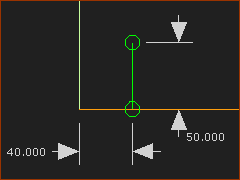
In this example, the new dimension will be 130 after you click Round
|
STEP 4: Complete the Command
1.Click to close the Dimension dialog |
STEP 5: Close the Part-Editor
There are many ways to close the Part-Editor. For example:
1.Double-click the Y-axis in the graphics-area |
|
 Round dimenson |
|
STEP 1: Edit the Base-Part
1.Double-Click the rectangle that is the Part-Outline of the Base-Part |
The Part-Editor is now open.
|
|
STEP 2: Add a Line

|
1.Expand the to the LEFT of the graphics-area
2.Click
Your pointer changes to the pointer.
a.Drag in the graphics-area |
The Line is now in the graphics-area
STEP 3: Add a Constraints and Dimensions
1.Click
a.Click the Line
2.Click
a.Click the start-Point of the Line
b.Click the X-axis
3.Click
Add Dimensions to the Line.
|
The Line is now Fully Constrained
|
|
|
STEP 4: Exit the Part-Editor
1.Double-click the Y-axis or the Line to exit the Part-Editor |
The Line and the Part in the Mechanism-Editor.
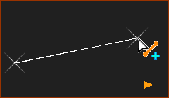
STEP 5: Add a Pin-Joint
1.Click the start-Point of the CAD-Line in the new Part of the CAD-Line in the new Part
2.Click the end-Point of the new Line that is in the Base-Part |
The Pin-Joint is now between the new Part and the Base-Part.
|
 Pin-Joint between Part and Base-Part |
|
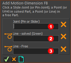
STEP 1: Start the Add Motion-Dimension FB command
|
1.Click |
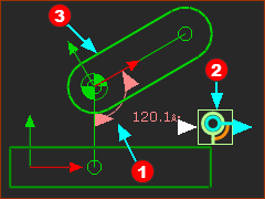
There are three selection-boxes in the .
Click in turn (see the image below)
Joint: Pin-Joint
Line - solved (Green) - a Line in a Part that is kinematically-defined
Line - free (Blue) - a Line in a Part that is not kinematically-defined
|
|
|
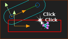
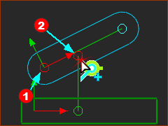
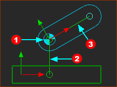
STEP 2: Select the three elements
Click in turn:
Pin-Joint
Line in the Base-Part - it is solved Line - the Base-Part is .
CAD-Line along the center of the new Part - it is not a solved Line - the Part is not kinematically-defined.
|
Important Notes:
STEP 3: Complete the Command
1.Click in the Command-Manager
OR
2.Right-click in the graphics-area |
The Motion-Dimension FB is now in the graphics-area.
The color of the Part-Outline is now green, to indicate it is kinematically-defined. - see Tutorial 1
|
 Command-Manager: Add Motion-Dimension |
The in the graphics-area.
|
|
Symbols for a in the graphics-area:
Motion-Dimension: the dimension value and dimension line with its arrowheads
Motion-Dimension FB icon.
The icon-design should help you see that it controls the angle of a Part.
CTRL + Drag the icon to move the Motion-Dimension with arrowheads.
Drag the icon to move only the icon
|
Notes on the new Part:
Derived Names
The Part is a kinematically-defined Part - its Mobility=0
The Part is a Motion-Part - because you can control its position with a Motion-Dimension FB3
It is a rotating-Part - because it is joined to another Part with a Pin-Joint3
It is a Rocker - which is the term we use in the Kinematic-Tree for a Motion-Part that is also a rotating-Part.
The of the new Part is green because the Part is .
|
|
