Basic Function-Blocks
Review the:
•Master Machine Angle
•Three of the basic Kinematic FBs that you use most frequently. You will use a Graph FB to plot the motion-values at the output connectors of each FB.
The Master Machine Angle is at the bottom and right of the application. When you Run/Cycle (ALT+C), the Master Machine Angle increases at a steady rate from 0 to 360, again and again.
To edit the Master Machine Angle (MMA): •Exact Angle: Enter a value in the MMA data-value box. Use your keyboard to enter a new value or use the spin-box tool. •Approximate Angle: Drag your mouse-pointer inside the MMA scale area |
Basic Kinematic Function-Blocks
To add these Function-Blocks (FBs) to the graphics-area:
1.Click the Function-Block you want to add to the model in the Function-Block menu (MD16 Add menu) or the Kinematic-FB toolbar 2.Click in the graphics-area. The Function-Block is in the graphics-area. |
|
The motion-values at the output-connector of the Linear-Motion FB increase linearly at the same rate as the MMA. Linear-Motion FB Output Angle ψ(º) = Master Machine Angle(º) + θ(º) Use a Linear-Motion FB to synchronize each kinematic-chain with the Master-Machine Angle.
|
|
The Gearing FB has three parameters:
•Step 1 = add •Step 2: = multiply Result 1 by the Gearing Ratio •Step 3: = add |
|
We use a Motion FB to link a motion in a Motion name-tab to a Motion-Part To link the Motion FB to a Motion name.
We design the motions in MotionDesigner, of course. |
Plot motion-values with a Graph FB
To find the motion-values at the output-connector of a FB, simply connect a wire from its output-connector to the input-connector of a Graph FB.
Remember, when you connect an output-connector to an input-connector with a wire, the motion-values are the same at the output-connector and the input-connector, because they see the same wire.
STEP 1: Add TWO Linear-Motion FBs to the graphics-area. STEP 2: Add a Graph FB to the graphics-area. STEP 3: Connect a Linear-Motion FB to the X-axis input of the Graph FB. STEP 4: Connect a Linear-Motion FB to one of the Y-axis inputs of the Graph FB. STEP 5: Edit the Linear-Motion FB that is connected to Y-axis of the Graph FB. STEP 6: Edit the Machine Angle + STEP 7: Edit the Graph FB to show the plot |
|
Below there is a screen capture of the various elements, carefully positioned, after Steps 1–7. There are two Linear-Motion FBs connected to a Graph FB. |
|
|
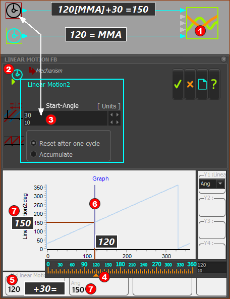
In the image to the left, the 'top' Linear-Motion FB is selected. It is connected it to the top (Y1) input of the Graph FB SETTINGS The dialog for the 'top' Linear-Motion FB is open Start Angle = +30 Master Machine Angle = 120
GRAPH CONNECTIONS: X-AXIS -'bottom' Graph connection The 'bottom' Linear-Motion FB is connected to the X-axis of the Graph FB. The Start-Angle of the 'bottom' Linear-Motion FB is '0'. Therefore, the input to the X-axis of the Graph FB is = MMA = 120 Y-AXIS – 'top' Graph connection The 'top' Linear-Motion FB is connected to the Y1-Axis of the Graph FB. The Start-Angle of the 'top' Linear-Motion FB is +30 Therefore, the input to the Y1-axis of the Graph FB is = MMA + Phase = 120 + 30 = 150 |
Digital Readouts (DROs) The DROs below the graphs indicate the values at the position of the vertical red cursor |
|
STEP 1: Add TWO Linear-Motion FBs to the graphics-area. STEP 2: Add a Graph FB to the graphics-area STEP 3: Connect a Linear-Motion FB to the Graph FB X-axis. STEP 4: Add a Gearing FB to the graphics-area STEP 5: Connect the other Linear-Motion FB to the Gearing FB, and from the Gearing FB to the Graph Y-axis. STEP 6: Double-click the Linear-Motion FB connected to the Gearing FB and edit the phase. STEP 7: Double-click the Gearing FB to edit the Gear parameters. STEP 8: Double-click the Graph FB to open it. |
|
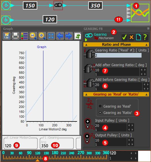
The Gearing FB dialog is open We have enabled Gearing as Ratio We have entered: •20 = Input Pulley •10 = Output Pulley •20 = Add Before Gearing Ratio •10 = After Gear Ratio Graph FB input-connections X-axis: The Linear-Motion FB is connected to the X-axis of the Graph FB It equals the MMA = 120 Y-axis: The top Linear-Motion FB is connected to the Gearing FB, which is connected to the Graph FB The output of the Linear-Motion FB is +30 The input to the Gearing FB = 120 + 30 = 150 The output from the Gearing FB and input to the Graph FB is: = (20/10)*(120+30)+20)+10 = 350. The Digital Readout (DRO) lists the values of the variables connected to the Graph FB. X-axis = 120 |
For Information: Gearing FB Output (when MMA 0) = 2 * ((0+30) + 20) + 10 = 110 Gearing FB Output (when MMA 360) = 2 * ((360+30) + 20) + 10 = 830 |
STEP 1: Add TWO Linear-Motion Function-Blocks to the graphics-area STEP 2: Add a Graph FB to the graphics-area STEP 3: Connect one Linear-Motion FB to the bottom input-connector of the Graph FB - the X-axis STEP 4: Add a Motion FB to the graphics-area STEP 5: Connect the Linear-Motion FB to the Motion FB, and from the Motion FB to the Graph FB STEP 6: Double-click the Linear-Motion FB that is connected to the Motion FB and edit the phase STEP 7: Double-click the Motion FB to link it with Motion in MotionDesigner STEP 8: Open the Graph FB |
|
|
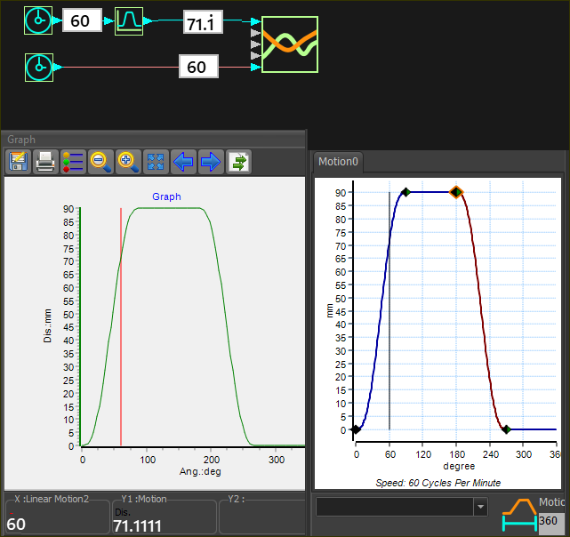
Top A wire connects: Linear-Motion FB to the Motion FB to the Y1 input of the Graph FB MotionDesigner is open to show the default motion that has a link with the Motion FB. The output from the Motion FB is 71.11. |
Bottom A wire connects: Linear-Motion FB to the Graph FB. The output from the Linear-Motion FB is equal to the Master Machine Angle (MMA). The output from the Linear-Motion FB is 60.
|
|
 Master Machine Angle (MMA) Slider @ is at 60.