Motion-Dimension FB
About the Motion-Dimension FB
A Motion-Dimension FB identifies a Part whose motion we want to control. Often, we say it is a Motion-Part. We control the position, velocity, and acceleration of a Motion-Part with two parameters: Base-Value (a parameter in the Motion-Dimension dialog ) This is the position of the Motion-Part when there is not a wire at the input-connector to the Motion-Dimension FB, or when the motion-value at the input-connector is zero. Motion-values (motion-values at the input to the Motion-Dimension FB) The motion-values control the position, velocity, and acceleration of the Motion-Part relative to a different Part. Motion-Dimension = Base-Value + Motion-Value There are two types of Motion-Part: •Rocker : Part + Pin-Joint + Motion-Dimension FB •Slider : Part + Slide-Joint + Motion-Dimension FB |
 Command-Manager: |
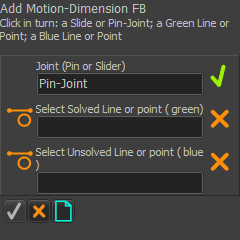
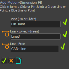
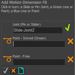
The Command-Manager has three selection-boxes. You must select these element-types:
if if
|
Prepare the model with these elements.
|
||||||||||||||||
 Preparation for a Rocker |
Preparation (typical):
STEP 1: Start the Command
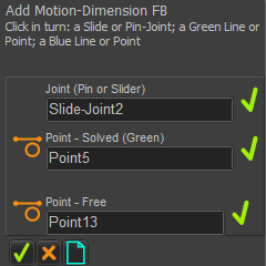
The Command-Manager indicates that there are three elements to select: STEP 2: Select the three elements in the graphics-area
STEP 3: Complete the Command
|
|||||||||||||||
|
||||||||||||||||
|
||||||||||||||||
 Rocker: kinematically-defined Part |
Result : a Rocker
|
|||||||||||||||
Note: There are two different mouse-actions to move the FB
|
||||||||||||||||
|
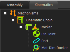
Kinematics-Tree for a Rocker When we add a Motion-Dimension FB to a Pin-Joint, the Motion-Part is a Rocker in the Kinematics-Tree. The kinematic elements are: Part + Pin-Joint + Motion-Dimension = Rocker |
|||||||||||||||
|
||||||||||||||||

Prepare the model with these elements.
* Line or CAD-Line |
||||||||||||||||
 A Sliding-Part |
Preparation example:
|
|||||||||||||||
|
STEP 1: Start the Command
The Command-Manager indicates that there are three elements to select. STEP 2: Select three elements in the graphics-area
STEP 3: Complete the Command
Result : a Slider
Note: There are two different mouse-actions to move the FB
|
|||||||||||||||
|
||||||||||||||||
 A Slider |
||||||||||||||||
|
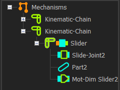
Kinematics-Tree When we add a Motion-Dimension FB to a Slide-Joint, we identify it as a Slider in the Kinematics-Tree. The kinematic elements are: Part + Slide-Joint + Motion-Dimension = Slider |
|||||||||||||||
|
||||||||||||||||
|
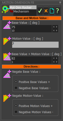
After you add the Motion-Dimension FB, you can open the Motion-Dimension dialog. To edit the Motion-Dimension FB: 1.Double-click the Motion-Dimension FB in the graphics-area The Motion-Dimension dialog is open. 2.Edit the: or oBase-Value + Motion Value The Base-Value is the position of the Motion-Part (Rocker or Slider) when the a wire is not connected to the input-connector of the Motion-Dimension FB, or the motion-value at the input-connector is zero.
Directions separator: •Edit the positive/negative directions of the Base-Value •Edit the positive/negative directions of the Motion-Values. |
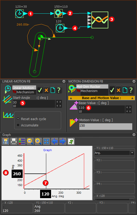
1.Add two Linear-Motion FBs 2.Add a Graph FB 3.Connect a wire from the Linear-Motion FB(1) 4.Edit the Base-Part and add a Line 5.Add a Part. 6.Add a Pin-Joint to join the start-Point of the Part to the start-Point of the Line in the Base-Part. 7.Add a Motion-Dimension FB 8.Connect the other Linear-Motion FB(2) 9.Double-click Linear-Motion FB(2) ; edit the Start-Value to 30 10.Double-click Motion-Dimension FB ; edit the Base-Value to 110 11.Double-click Graph FB to show the plot. |
|
In the image, the Master-Machine-Angle (MMA) is 120º. Thus, the output from the Linear-Motion FB The Base-Value The angle of the Rocker is Base-Value + Motion-Value = 110º + 150º = 260º. The output from the Motion-Dimension FB is the input to the Graph FB. When you open the Graph FB, the vertical cursor If you set the cursor The graph is a plot of the output of the Motion-Dimension FB (Y-axis) against the MMA (X-axis) |