Cranks, Rockers, Sliders
In this step, we connect these Function-Blocks (FB):
•A Linear-Motion FB
•A Motion-Dimension FB
•A Motion FB and a Gearing FB
These FBs, together, control the motions of Crank, Rocker and Sliders.
+
+
|
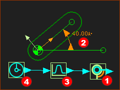
A Rocker is a Part that rotates around a Pin-Joint. Motion-values at the input-connector to a Motion-Dimension FB controls the position and motion of the Rocker. |
|
|
To add a Rocker:
To edit the FBs, double-click the FB icons, or see How to open an Element's dialog. |
|
'Expand' then 'Play'
|
||

+
|
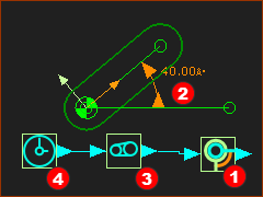
A Crank is a derived term for a Rocker that rotates at constant speed. |
|
|
The Crank:
|
|
+
+
|
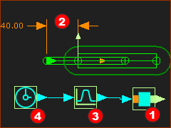
A Slider is a Part whose motion is controlled to move along a Slide-Joint. |
|
|
To add a Slider:
|
|
'Expand' then 'Play'
|
||