Objective of this Step 8.1
To learn the terminology that we use in MechDesigner. To review the elements that we use to import and display a DXF-Drawing. |
Terminology of DXF related elements
Term : |
Definition |
|---|---|
DXF : |
Drawing EXchange Format. DXF is a CAD data file format designed for sharing drawing data universally across CAD applications. |
DXF-Drawing : |
The original drawing that you want to import from your CAD and display in MechDesigner. |
DXF-Element : |
The DXF-Element is the container for the original DXF-Drawing that you import when you do File menu > Open | file of type DXF. The DXF-Element is in the Assembly-Tree. |
CAD-Line : |
The element that you edit to display a DXF-Drawing. |
DXF-Outline : |
The efficient reference sketch that we use to display a DXF-Drawing. You cannot edit a DXF-Outline. |
DXF-Entity : |
Points, Arcs, and Lines are entities in the reference sketch of the DXF-Outline. You can use the CAD-Line dialog to convert Arc and Lines in a reference sketch to regular Arc and Line sketch-elements. |
DXF-Element
To import a DXF-Drawing do: 1.File menu > Open | DXF file type We add for you a DXF-Element to the Assembly-Tree. The DXF-Element is the container for the DXF-Drawing. |
DXF Element in the Assembly-Tree
 DXF-Elements in the Assembly-Tree The DXF-Element - |
MD17+: The name of the DXF Element is the file-name of the DXF drawing. |
Open the DXF-Element dialog:
1.Double-click a DXF-element in the Assembly-Tree. or |
The DXF-Element dialog
 DXF-Element dialog |
The DXF-Element dialog shows the:
To replace the DXF-Drawing with a different DXF-Drawing:
DXF Units
Close the dialog:
|
CAD-Line element
Each Part you add to the model has a CAD-Line You can add more CAD-Lines to Parts and the Base-Part. 1.Edit a Part or the Base-Part 2.In the Part-Editor, click Geometry toolbar > Add CAD-Line 3.Drag your mouse. |
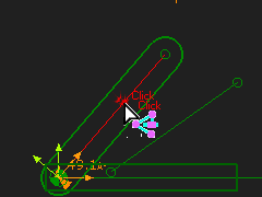
CAD-Line in the graphics-area
 CAD-Lines in the Graphic-Area |
|
CAD-Line in the Assembly-Tree
 CAD-Lines in a Part in the Assembly-Tree |
CAD-Line : in the Assembly-Tree
|
To edit the CAD-Line
 |
To edit a CAD-Line:
The CAD-Line dialog is now open. |
CAD-Line dialog >DXF tab

CAD-Line dialog > DXF tab
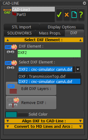 |
Select which DXF-Element : DXF-Drawing you want the CAD-Line to display:
If you cannot see the DXF-Drawing, try to find it.
There are two buttons
|
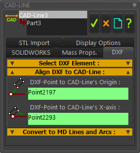 |
Default Alignment of the DXF-Drawing with the CAD-Line The DXF-Drawing aligns its 0,0 and positive X-axis with the start-Point and positive X-axis direction of the CAD-Line. The default alignment may be as you intend. However, you can edit the alignment of the DXF-Drawing relative to the CAD-Line. To re-align the DXF-Drawing:
|
Convert DXF to MD Lines and Arcs
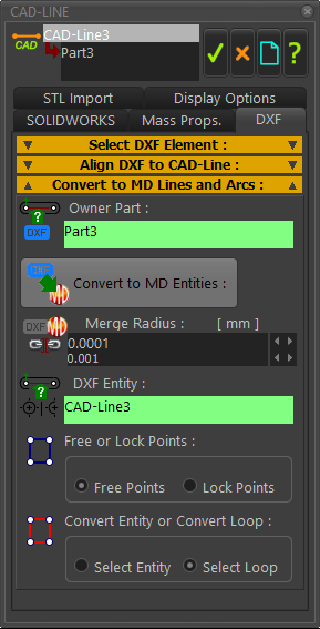 |
To Convert a DXF Entity to a sketch-element:
Notes: When you press the button, the new sketch-elements do not have a link to the CAD-Line; they have a link to the Part. Therefore, you can press the button (in the Select DXF Element separator) to remove the DXF-Drawing from the CAD-Line, but the sketch-elements stay with the Part. |