Kinetostatic vs Dynamic Analysis - a definition
MechDesigner does Kinetostatic Analyses1.
That is, MechDesigner calculates the forces at joints between Parts that arise when you impose a motion on a kinematic-chain, when those Parts have mass and mass moment of inertia. MechDesigner moves the Parts in the kinematic-chain exactly with the motion that you design for them. We can say that MechDesigner moves the Parts with an idealized or perfect power source2.
A Dynamic Analysis calculates the resulting motions of a mechanism from a force or torque that is imposed on the mechanism with parts that have mass and mass moment of inertia.
MechDesigner does the Kinetostatic Analysis of each kinematic-chain.
MechDesigner 17+ also does a Dynamic Analysis.
Notes:
1.Force: is a generalized force, which will includes Torques/Moments.
2.An Idealized Power Source moves the mechanism perfectly, and exactly as planned. A simple example of an Idealized Power Source is the motion of a cam-shaft that you want to rotate with a constant angular-velocity. In a real system, the angular-velocity of the cam-shaft will change slightly when the torque fluctuates on the cam-shaft as it rotates.
About Kinetostatic Forces
Kinetostatic-Forces: •Forces at joints •Forces at anchor points of Springs •Forces at the contact point between gear teeth flanks, and between a cam-profile and follower-profile •Force or Torque to move each kinematic-chain with a predefined motion Kinetostatic-Forces are a function of: •The motion of Parts: Inertia force, Centripetal force, Coriolis force. We assume the motions of all Parts move exactly as planned •The Mass distribution: Mass, Center-of-Mass, Mass Moment of Inertia •External Forces: Spring, Drag, Coulomb Forces, ... •Gravitational Force: when the Mechanism-Plane is not horizontal •Which joint drives the kinematic-chain. See: Why Configure the Power Source •Friction-Forces in a joint, which are difficult to model exactly Kinetostatic-Forces do not include: •Impact Forces of Parts that collide •Impact Forces after traversal of backlash in Joints, Gear-Pairs or Cam-Tracks •Friction Forces •Magnetic, Electrical Forces |
Kinetostatic-Forces are for Ideal Kinematic-Chains.
IDEAL KINEMATIC-CHAINS: •Rigid Parts do not bend, twist or stretch •Rigid Parts do not expand with temperature •Rigid-Part have an exact length, without a tolerance •Joints do not have play (backlash) •Joints do not have Friction •Power Source is idealized - it moves exactly as planned •Surfaces at Cams and Gears do not deflect |
REAL KINEMATIC-CHAINS: •Real Parts: do deflect, twist and stretch •Rigid Parts: do expand with temperature •Rigid Parts: do have a tolerance to their length, plus other geometric constraints (GD&T) that need to be applied •Real Joints: do have backlash, play •Real Joints: do have friction •Power Sources do not move exactly as planned •Real contact surfaces do deflect •Real kinematic-chains: are not 100% efficient •Real kinematic-chains vibrate |
You may think “Why do a model when it can deviate from the Ideal Kinematic-Chain by so much”? However, the better your design, the nearer it will be to the Ideal Kinematic-Chain. |
|
It is important that you Configure the Power Source correctly for each kinematic-chain before you do a Kinetostatic Analysis. Each kinematic-chain has three different possible Power Sources.
|
| Example - moving the Power-Source to a different joint. |
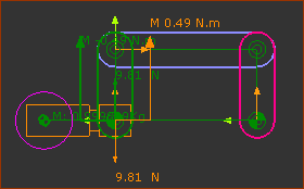
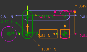
This example shows how the force in each joint changes when you move the Power-Source to a different joint in a kinematic-chain. The example uses a “parallel” four-bar kinematic-chain. The four-bar includes a: Motion-Part. •Rocker - the Rocker is the vertical Part on the left. It is joined to the Base-Part with a Pin-Joint. •The Rocker has a 1kg mass which is 50mm to the left of the Pin-Joint. The weight (Gravitational Force) of the 1kg mass is + ~9.81N (1kg * 9.81m/s/s = 9.81N). R-R-R dyad (two Parts, three Pin-Joints) •one of the two Parts is is horizontal, the other Part is vertical and parallel to the Rocker. •the Parts are joined together, to the Base-Part, and to the Rocker, with Pin-Joints. |
|
 Configure Power Source to the Left |
Configure Power Source 1: LEFT Pin-Joint with the Base-Part Resolve Forces: 9.81N Vertical Down Gravitational Force Down 9.81N Vertical Up Reaction Force at Pin-Joint The Forces at all of the other Joints are ZERO. Resolve Moments: 0.49Nm Counter Clockwise Torque from the weight of the Mass at 50mm from Pin-Joint. 0.49Nm Clockwise Torque from the Motor that acts-on the Rocker to balance the Weight |
 Configure Power Source to the Right |
You can move the Power-Source to a different Pin-Joint. Configure Power Source 2: Right Pin-Joint with the Base-Part Resolve Forces: Vertically and horizontally to give forces at the Pin-Joints. The force due to the mass is transmitted through the kinematic-chain to the Power-Source. Resolve Moments: Resolve Moments gives the same Moment (Torque), but at the Pin-Joint on the right.
You can see that the Forces for 1 are different to 2. |