Forces that ACT ON a Rocker.
To understand how we calculate and show the Forces Vectors, we will start with a basic kinematic-chain.
•The kinematic-chain is a Rocker.
•The Base-Value of the Motion-Dimension FB controls the angle of the Rocker.
•The Motion-Dimension FB does not have a wire connected to its input-connector.
•We add a Profile / Extrusion to the Rocker, The Extrusion has mass and inertia.
Add the Model
 with Forces Display ON") A Rocker with Center-of-Mass Symbol(1) with Forces Display ON |
STEP 1: Add a Rocker
|
|
STEP 2: Add a sketch-loop, and a Profile/Extrusion.
|
||
Calculate and Display the Force Vectors
There are two icons in the Forces menutoolbar: Calculate and Display Force Vectors. |
|
|
Mechanism-Editor: Click Force toolbar > Calculate Forces |
|
Mechanism-Editor: Click Force toolbar > Display Force Vectors |
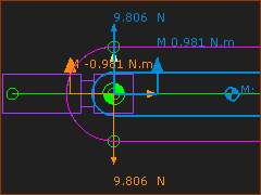
When a minimum of one Part has mass, we calculate for you and we display Force Vectors. The Force-Vectors give the direction, location, and magnitude of each Force. Notes Use the Force and Torque Vector Scale buttons to increase or decrease the length of the vectors if they are too long or too short to see easily. |
|
Analyze the Forces
|
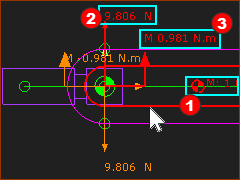
Force Analysis - Information Provided:
|
|||
|
||||
Move your mouse-pointer to the Part-Outline of the Rocker. The Force-Vectors that ACT ON the Rocker are now Red. Vertical Forces (N) acting on the Rocker - Upwards is +ve
Moments (N.m) at the Pin-Joint - Counter-clockwise is +ve
Force explanation of the RED Force Vectors and Moments
|
||||
|
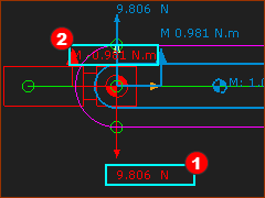
Now move your mouse-pointer to the vertical Force-Vector that acts on the Base-Part. All vectors that ACT ON the Base-Part turn Red.
It is the Gravitational Force of the Rocker that acts-on the Base-Part.
|
|||
|
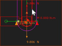
Edit the Motion-Dimension FB to rotate the Rocker until it is vertical •My mouse-pointer is above the Part-Outline of the Rocker - the Part-Outline and the Force-Vector become Red. • Vertical Force = 9.807N. (upwards) This is the same vertical force as when the Rocker was horizontal. This is not a surprise. The Part has the same mass and it is the only joint through which the force can act. •Torque Moment = 0Nm The Center-of-Mass of the Rocker above the Pin-Joint. Therefore, the Rocker does not need a Torque to hold it in the vertical position. |
|||