Motion-Law: Y–Inverse-Sinusoid

<< Click to Display Table of Contents >>

Navigation:  MotionDesigner Reference & User Interface > Motion Laws / Cam-Laws for Segments >

Motion-Law: Y–Inverse-Sinusoid

Y–Inverse-Sinusoid

Note: The Y-Inverse-Sinusoid motion-law is usually applied to a rotating part, e.g. a Crank. There can be only one Y-Inverse-Sinusoid segment in each motion.


See also : Constant Crank Velocity

Motion-Description

We can explain this motion-law if we project the motion of a Point that is at the end of a rotating Crank onto a Line.

When a Crank rotates with Constant angular velocity, the motion of a Point that we project onto any Line is Simple-Harmonic-Motion.

When the Crank rotates with the Y-Inverse-Sinusoid motion-law, the motion of a Point that we project onto a particular Line is Constant Linear Velocity.

Motion-Values

You CAN control the:

Start-Position - control with the Segment-Parameters - see below.

End-Position - control with the three Segment-Parameters - see below.

You CANNOT control the:

Start Velocity and End Velocity

Start Acceleration and End Acceleration

Start Jerk and End Jerk

Segment Parameters

Example Segment Parameters

Example Segment Parameters

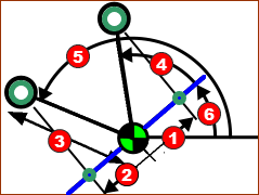
Schematic of Crank made to give a constant linear velocity from Angle(4) (defined by Start-Position(1), to Angle(5), defined by the End-Position(2).

Schematic of Crank made to give a constant linear velocity ...

AngleRed-14-6 is to Blue line relative to any other line, as defined by the Base-Value of the Motion-Dimension FB.

Radius of Rocker (Example is 100mm)

The Radius of the Rocker (rotating-Part) controls the minimum and maximum distance from the rotating-axis of the Green point, at the end of the Rocker, projected onto the Blue line.

Start-PositionRed-14-1b (Example SP=–50mm)

Directional Distance from the rotating-axis of the Green point projected onto the Blue line when the Green point starts to move with Constant-Velocity along the Blue line.

End-PositionRed-14-2 (Example EP = 50mm)

Directional Distance from the rotating-axis of the Green point projected onto the Blue line when the Green point ends moving with Constant-Velocity along the Blue line.


We calculate for you the angles Red-14-4 and Red-14-5 for the Rocker relative to the Blue Line, from the Start-Position and End-Position.

Note:

The Crank rotates Counter-Clockwise when Start-Position is Negative and End-Position is Positive.

The Crank rotates Clockwise when End-Position is Negative and Start-Position is Positive.

Segment-Range

Start-Range

End- Range

0 ≤ Start-Range < End-Range ≤ 1


Video: Y-Inverse-Sinusoid Example

Y-Inverse Sinusoid

Y-Inverse Sinusoid

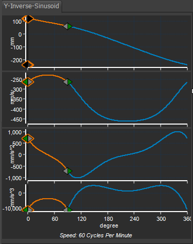
Example: with two segments.

Crank rotates in a Counter-Clockwise direction

Constant-Velocity Starts at 50mm to Left of Crank-Center (angle 120º)

Constant-Velocity Ends at 50 to Right of Crank-Center (angle 60º)

Segment 1:

X-axis Start = 0 ; End = 90º

The Y–Inverse Sinusoid Segment-Parameters are:

Radius of Rocker = 100mm, Start Position = -50, End Position = 50mm.

With these Segment-Parameters:

The Y–axis is 120º†, when the Master Machine Angle (MMA) is 0º .

The Y–axis is 60º, when the Master Machine Angle is 90º .

Segment 2:

X-axis Start = 90º, End = 360º (0º)

A Flexible-Polynomial

The Y–axis is 60º, when the Master Machine Angle is 90º (= end of Segment 1)

The Y–axis –240º when the Master Machine Angle is 360º .

Thus the Crank makes a full rotation from +120 to -240 in a counter-clockwise direction.