In this Tutorial
The kinematic-chain of a four-bar in the Kinematics-Tree is a Rocker and an R-R-R dyad. Its Mobility is zero.
In this tutorial we will add to the four-bar one more R-R-R dyad.
These six-bar mechanisms have names, taken from famous inventors of the 18th and 19th centuries.
•Watt 1 and 2
•Stevenson 1, 2, and 3.
In each case, because the Mobility of the four-bar is zero before we add a dyad, it is also zero after we add a dyad.
A dyad does not change the Mobility of a kinematic-chain.
Objective of the Tutorial
Add an R-R-R dyad to the four-bar. 1.This four-bar is: a Rocker and R-R-R dyad - see Step 2A 2.Add a new R-R-R dyad. |
|
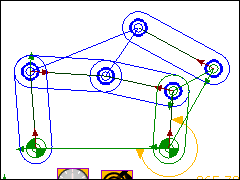
") A four-bar (Rocker + R-R-R) |
We have a four-bar similar to this model - see image to the left. The four-bar has a Rocker (1), which is the Motion-Part, and an R-R-R dyad. The Motion-Part(1) has a motion relative to 4 - the Base-Part. The R-R-R dyad consists of Parts 2 and 3, and Pin-Joints, R1, R2, R3. Remember, a Pin-Joint is equivalent to a Revolute Joint, hence the letter R for Revolute, and hence the R-R-R dyad. |
The Classic Six-Bar Mechanisms
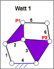
Watt 1
|
Watt 1
|
|
|
STEP 1: Add Points P1 and P2:
|
|
|
STEP 2: Add the R-R-R dyad
|
|
6-Bar Mechanism Watt 1 |
Example Watt 1 Mechanism: Cabinet Hinge Mechanism |

Watt 2
|
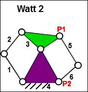
Watt 2 The 'standard' four-bar kinematic-chain is Parts - 1,2,3,4. The extra dyad, Parts 5 & 6, is joined to the Rocker, Part 3, and the Ground, Part 4. |
|
Edit Parts to add Points P1 and P2. You can add a Point, or a sketch-element with a Point. For example: add two lines to the Frame and two Lines to the Rocker to give a triangle in each Part. The apex of each triangle give the Points: P1 and P2. |
|
Add the R-R-R dyad Add two Parts: 5 & 6. Join one Part to P1, the other to P2, then join the two Parts, 5&6, together. |
Stephenson 1
|
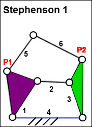
Stephenson 1 The 'standard' four-bar kinematic-chain - Parts 1,2,3,4. The extra dyad, Parts 5 & 6, is joined to the Crank, Part 1, and the Rocker, Part 3. |
|
Edit Parts to add Points P1 and P2. Add two lines to the Rocker and two Lines to the Crank to give a triangle in each Part. Each triangle gives the Point: P1 and P2. |
|
Add the R-R-R dyad Add two Parts: 5 & 6. Join one Part to P1, the other to P2, then join the two Parts, 5&6, together. |
Stephenson 1 Mechanism: Car Hood. |
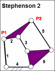
Stephenson 2
What does a Stephenson 2 look like? |
|
|
It is not possible to make this a kinematically-defined chain. You can connect the Parts, but they can not be kinematically-defined! |
|
The Stephenson 2 cannot be solved by MechDesigner. Can you see why? The Parts and Joints move correctly, but not as quickly as when the Parts have all kinematically-defined. |
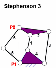
Stephenson 3
|
Stephenson 3 Similar to the Watt 1. The Watt 1 has a dyad across the(Output) Rocker and the Coupler. The Stephenson 3 has a dyad across the (Input) Crank and the Coupler The 'standard' four-bar mechanism with four Parts - 1,2,3,4.. + the R-R-R dyad, the two Parts 5 & 6. Part 5: Part 6: Edit Parts 2 and 4 to add Points P1 and P2. Add two lines to the Coupler and two Lines to the Frame to give a triangle in each Part. Each triangle gives the Point: P1 and P2. Add the R-R-R dyad Add two Parts: 5 & 6. Join Part 5 at Pin-Joint, P1, Joint Part 6 at Pin-Joint, P2, Parts 5 & Part 6, to each other, with Pin-Joint. |
|