Import DXF Drawing of Cam
We describe how to import a DXF drawing.
Prepare the model
Ideally, the MechDesigner model represents the Cam and the Follower's kinematic-chains in the machine.
The Cam-Part may be rotating, sliding, stationary, or it may have a complex motion. In this model, we will assume the cam rotates on a cam-shaft.
|
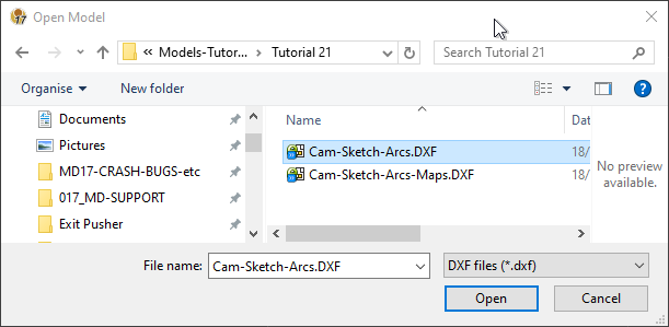
We can represent the cam-shaft with a rotating-Part. STEP 1: Open / Import the DXF Drawing into the Assembly-Tree. 1.Select File > Open 2.Select DXF files as the file of type. 3.Browse to find the file 4.Click Open |
|
|
|
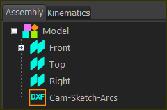
The DXF element is now at the bottom of the Assembly-Tree. It has the name of the DXF Drawing.
|
|
STEP 2: Edit the CAD-Line to add the DXF Drawing to the CAD-Part 1.Edit the CAD-Line along the Cam-Part. The CAD-Line dialog is now open. |
|
STEP 2:
|
|
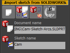
5.Click the Import SolidWorks sketch button. |
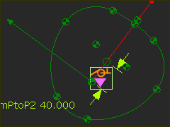 |
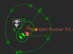
WAIT: Sketch in Part-Editor: •The Points are 'fixed' •There are no dimensions •There are no constraints or relations. |
|
6.Exit the Part-Editor Sketch in Mechanism-Editor |
|
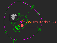
7.Add a Profile element to the the Import SolidWorks sketch button. The Profile contours are Pink. You do not need to Show Solids in Mechanism. |
|
|
