Prepare the Sliding-Part
We add a Slider, and a rotating Cam to move the Slider as a Translating-Follower.
|
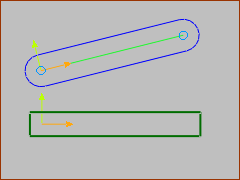
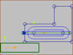
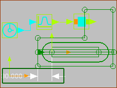
STEP 1: Add a Mechanism, Part and a Sketch for the Tool-Part. In the Mechanism-Editor: 1.Model-Editor: Click Model toolbar > Add Mechanism | Click a Plane You will jump to the Mechanism-Editor 2.Mechanism-Editor: Click Kinematics toolbar > Add Part | Drag to add a Part.
|
|
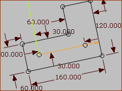
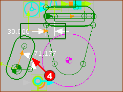
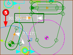
3.Mechanism-Editor Edit the Part. 4.Part-Editor: Add a similar sketch in the image to the left. The sketch must be a sketch-loop. 5.Close the Part-Editor |
|
STEP 5: Edit the Base-Part STEP 6: Add a Line to the Base-Part, and Horizontal, and Add a Dimension. STEP 7: Close the Part-Editor.
The Base-Part is a kinematically-defined Part. It is a Green Part. The new Part is not yet a kinematically-defined. It is a Blue Part. It is also called a Free-Part. |
|
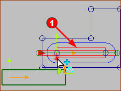
STEP 1: Click Kinematic-elements toolbar > Add Slide-Joint |
|
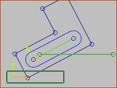
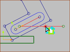
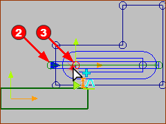
STEP 2: Click the CAD-Line along the Blue Part (the CAD-Line is Red in the image). STEP 3: Click the Line in the Base-Part - see mouse-pointer in the image
|
|
To remind you: the Symbol of the Slide-Joint is: 1.Two rectangles that extend along the full length of each Line that you select to add the Slide-Joint. In this image, the: •a thin rectangle - which we can imagine as the Slide-Rail •a wider rectangle (- which we can imagine as the Sliding-Block 2.A small arrowhead at the start-Point of one of the two Lines. The arrowhead is in the positive direction of the Slide-Joint. |
|
STEP 1: Kinematic-FB toolbar > Add Motion-Dimension FB. |
||||||
|
Reminder: You can add a Motion-Dimension FB to a Pin-Joint or a Slide-Joint, to make a Rocker or Slider respectively. The Command-Manager has three selection boxes: STEP 2: Click the Rectangle When you select a Slide-Joint as the Element #1 •Element #2 must be a Point in a Green Part •Element #3 must be a Point in a Blue Part |
||||||
|
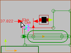
STEP 3: Click the start-Point STEP 4: Click the start-Point STEP 5: Right-click - to complete the command, close the Command-Manager, and add the Motion-Dimension FB. |
||||||
|
Now, the Part is Green and a kinematically-defined Part. We call it a Slider. STEP 6: Double-click the Motion-Dimension in the graphics-area STEP 7: Motion-Dimension dialog | Enter Base-Value = 30(mm) Note: To drag / move in the graphics-area, the:
|
||||||
|
Add the Function-Blocks and connect: STEP 8: Click Kinematic-FB toolbar > Add Motion FB and then click the graphics-area STEP 9: Click Kinematic-FB toolbar > Add Linear-Motion FB and then click the graphics-area STEP 10: Connect the Function-Blocks. If you cycle the model (ALT+C ), the Slider moves with the default motion of 90mm. As its Base-Value is 30mm, it will move from 30mm to 120mm to 30mm with each machine-cycle. |
We rotate a 2D-Cam to drive the slider back and forth. |
|
|
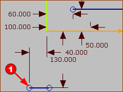
Add the sketch for the center of a cam-shaft to the Base-Part. STEP 1: Edit the Base-Part STEP 2: Geometry toolbar > Add Line STEP 3: Constraints toolbar > Add Horizontal to the Line You can see the new Blue Line at the bottom. It is Blue because we have not yet specified its Length. |
|
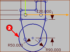
We can add to it a bracket to support the Follower-Roller. The Follower-Roller is a circle of Radius 90mm STEP 3: Edit the Slider Part STEP 4: Geometry toolbar > Add Circle STEP 5: Exit the Part-Editor
|
|
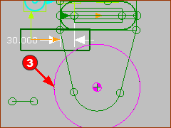
STEP 3: Solids toolbar > Add Profile STEP 4: Click the Circle This is the Follower-Roller. |
|
Add a Cam-Shaft that rotates one time per machine cycle. This is Tutorial 1. Use the Line in the Base-Part as the center of the cam-shaft. STEP 5: Click Kinematic elements > Add Part STEP 6: Click Kinematic elements > Add Pin-Joint | Click the start-Point of the Line in the Base-Part and the start-Part of the new Part. STEP 7: Click Kinematic FB > Add Motion-Dimension FB | Click the Pin-Joint, the Line in the Base-Part and the CAD-Line along the Part. STEP 8: Click Kinematic FB > Add Linear-Motion FB and the graphics-area. STEP 9: Connect the Motion-Dimension FB and the Linear-Motion FB |
|
Add the 2D-Cam STEP 1: Click Machine elements > Add 2D-Cam. STEP 2: Click the Cam-Shaft STEP 3: Click the Cam- Roller STEP 4: Click The new 2D-Cam If you cycle the model, the 2D-Cam rotates one time as the Slider moves one motion cycle. |
