Key Learnings:
Hopefully, we will learn a new concept. In this tutorial:
... the motion of the Rocker is a function of the position of the Slider
... the motion of the Rocker is NOT a function of the motion of the MMA
We will add the 2D-Cam to the Base-Part. The Rocker is joined to the Slider. The Slider move along Base-Part as the 2D-Cam moves the Rocker.
Note: There is an alternative: we can join the Rocker to the Base-Part, and move the 2D-Cam with the Slider.
First: What do we want the Cam to look like?
|
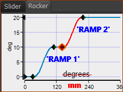
<<< Rocker motion in MotionDesigner prepared for the Rocker in Step 6D1.2 The Rocker motion has 5 segments - Dwell - Rise - Dwell - Rise - Dwell For convenience we will call it a DRDRD motion. IMPORTANT NOTE We should imagine that the X-axis Units are mm. Then, it is easy to imagine that the X-axis is equal to the Linear Position of the Slider in mm. |
|
Let's look ahead: This 2D-Cam We will look at four methods to add the 2D-Cam. We will explain the problems and advantages of each. •Method 1: This method is useless, it will not give you the cam you want! •Method 2: OK •Method 3: Success for Single-axis Machines •Method 4: Success for Multi-axis Machines |
 Method 1: Add the 2D-Cam (as you would normally)
|
Add a Profile to the circle for the Follower-Roller. |
|
STEP 1: Click Solids toolbar > Add Profile STEP 2: Click the Circle in the Rocker Part | Click There are two terms that we will use. •Follower-Profile : the Profile that is in contact with the Cam. •Follower : the Part to which we add the Follower-Profile |
|
STEP 3: Click Kinematic FB toolbar > Add 2D-Cam |
|
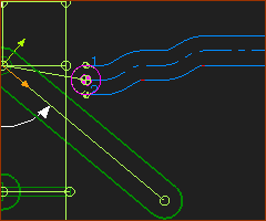
We must click two elements: STEP 4: Click the Base-Part STEP 5: Click the Follower-Roller Profile Click The Cam does not look like the Rocker motion!
|
|
It is often easier to view the Pitch-Circle-Path: STEP 6: Edit the 2D-Cam STEP 7: 2D-Cam dialog: Display tab > Cam Visibilities > Click Pitch-Curve check-box, Clear INSIDE 1 and OUTSIDE, GROOVE check-boxes. (Inside and Outside Cams in MD16+)
|
|
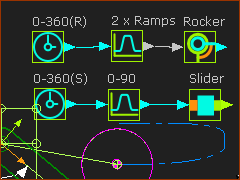
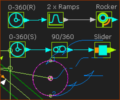
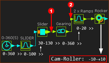
The Function-Blocks have been connected as: MMA(0-360) > Motion-FB(DRDRD Motion) > Rocker MMA(0-360) > Motion-FB(0-90) > Slider The input to the Motion FB for the Rocker Part is 0 to 360 Therefore, its output is the Dwell-Rise-Dwell-Rise-Dwell motion
|
IMPORTANT CONCEPT If we delete the wire at the input to the Motion-Dimension FB that controls the position of the Slider, the Slider will not move - obviously. However, the Rocker will do its motion. Why?. Because the input to the Motion-Dimension FB is the from the Motion FB. The input to the Motion FB is from Linear-Motion FB, which equals the MMA. However, the Rocker should not move when the Slider is stationary. |
|
 Method 2: 'Motion' from MMA as input to the Slider
Method 2: move the Slider at Constant-Velocity. |
|
|
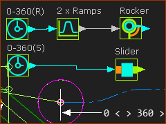
Continue from Method 1: STEP 1: Delete the wire that is at the input to the SLIDER Motion-Dimension FB STEP 2: Connect the Linear-Motion FB directly to the Slider Motion-Dimension FB. <<< see image The input to the Slider is now 0 -360. The Slider will move horizontally from 30mm (Base-Value) to 390mm (Base-Value + Motion-Value) with Constant-Velocity. It then instantly moves back to 30mm after each 0-360 cycle of the MMA. |
|
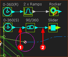
However, the motion-design of the Slider has a motion-range (as intended) of 90mm. We want to move the Slider from 30mm to 120mm. To reduce the output from the Linear-Motion FB from 360 to 90mm, we can use a Gearing FB. STEP 3: Click Kinematics FB toolbar > Add Gearing FB and then click the graphics-area STEP 4: Delete the wire that is from the Linear Motion FB to the Motion-Dimension FB (Slider) STEP 5: Connect a wire STEP 6: Connect a wire
|
|
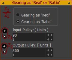
STEP 6: Edit the Gearing FB STEP 7: Gearing FB dialog: Gearing as Real or Ratio > Gearing as Ratio : Input-Pulley=90 / Output-Pulley=360
|
|
When look at Cam 1 and Cam 2 - and not only the Pitch-Circle, there is serious undercutting of the Cam.
|
|
STEP 8: Edit the radius of the Follower-Roller to R7mm STEP 9: Edit the length of the rotating lever that is the Follower to 40mm
Now the stationary cam has 2 × Ramps is as we intend it to be. Excellent. ... However, ... |
Question 2: Why is it not an excellent result? Answer 2: The Slider Cam looks like a 'Snail'! The Slider moves at constant-velocity in one direction, and then jumps back to zero. It does not have the motion-design Slider that is in MotionDesigner.
We want the 2D-Cam for the Slider AND the Stationary 2D-Cams. <<< Click the image to expand and collapse. |
|
 Method 3: Connect the Slider the Rocker
As stated above. We want a Cam to rotate the Rocker and also a Cam to move the Slider. |
||
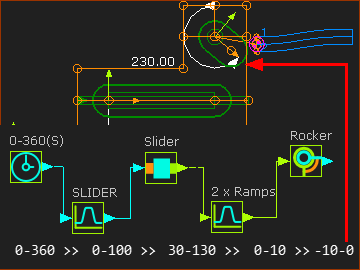 |
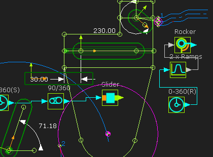
We will add all of the wires again. STEP 1: Delete all of the wires STEP 2: Connect a wire from a Linear-Motion FB to the Slider Motion FB Its output is, of course, the Slider motion that we have designed in MotionDesigner ( a Range of 0-100) STEP 3: Connect a wire from the Slider Motion FB to the Slider Motion-Dimension FB Its output controls the Slider Part - which will move by the BASE-Value(30) + Motion Values . ( a Range of 30-130) This is the normal way to connect a Motion-Part.
This is the IMPORTANT STEP! |
|
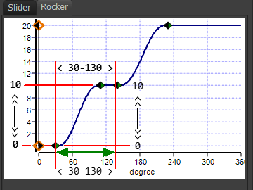 |
STEP 1: Connect the output from the Slider Motion-Dimension FB to the input of the Rocker Motion FB. The input to the Rocker Motion FB now has a motion-range from 30 -100. This is equal to the X-axis of the motion in the Rocker name-tab in MotionDesigner. The image to the left indicates the input range, or the X-axis motion-values, on the Motion graph, which is at the input to the Rocker Motion FB The motion-values (30 to 130) increase from 30 to 130 and then decrease again from 130 to 30 - exactly as does the Slider motion. The output motion-values from the Motion FB have a range of 0 to 10 - the Y-AXIS of the motion in the Rocker motion name-tab. STEP 2: Connect the output from the Rocker Motion FB to the input of the Rocker Motion-Dimension FB The input to the Rocker Motion-Dimension FB is 0 to 10(Y-axis of Rocker motion). To find the angle of the Follower relative to the X-axis, we simply need to add up these values. The Motion-Dimension is relative to the vertical line in the Slider Part =+90°, the Motion-Dimension FB > Base-Value = +230°, the Line for the Follower in the Rocker Part is at +30° .Thus +90+230+30 =350° or -10° Thus, the Motion-Range, relative to the X-axis, rotates the Follower from -10 to 0. |
|
Note: You will get a message in the Feedback area: “Mechanism dependencies detected”. It is advisable to rebuild the model when the number of dependencies is more than 1. The Slot-Cam looks near to complete. However: it is not complete? The motion-values at the input (the X-axis) to the Rocker Motion FB have a motion-range = 30 - 130. We want the motion-range at the input (X-axis) of the Rocker Motion FB to be 0 to 360. Thus, we need to move the starting point of the input(X-axis) from 30 to 0, and the maximum value to 360, but still be a function of the output from the Slider Motion-Dimension FB |
||
|
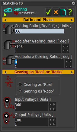
We can use a Gearing FB. STEP 1: Add a Gearing FB. STEP 2: Connect a wire STEP 3: Connect a wire STEP 4: Edit the Gearing FB to open the Gearing FB dialog. STEP 5: Gearing FB dialog > Gearing as Ratio : Input Pulley =360 : Output Pulley=100 The range of values at the output-connector of the Gearing FB is now 360 |
|
However, ... •The Output from the Slider Motion-Dimension FB 30 – 130, (as the Base-Value = 30mm). •The Minimum Output from the Gearing FB: •When the input to the Gearing FB is 30, its output is 30 * 360/100 = 108 •When the input to the Gearing FB is 130, its output is 130 * 360/100 = 468. •The input to the 2 × Ramps Motion FB is 108 - 468, not from 0 - 360. •It needs to be 0–360, not 108–468. To correct this offset we can use one of two possible other parameters in the Gearing FB. |
||
|
Add After Gearing Ratio This parameter is added after the input is multiplied by the Gearing-Ratio Thus if we enter the -108 •When the input to the Gearing FB is 30, its output is (30 * 360/100)-180 = 0 •When the input to the Gearing FB is 130, its output is (130 * 360/100)-108 = 360. •The input to the 2 × Ramps Motion FB is 0 - 360 Add Before Gearing Ratio This parameter is added before the input is multiplied by the Gearing-Ratio Thus if we enter the -30 •When the input to the Gearing FB is 30, its output is (30-30) * 360/100 = 0 •When the input to the Gearing FB is 130, its output is (130-30) * 360/100-108 = 360. •The input to the 2 × Ramps Motion FB is 0 - 360 Thus, we get the same result in the two cases. <<< The Gearing FB parameters. |
|
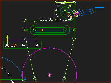 |
We can see that the Slot-Cam now has the correct-profile. |
|
 Method 4: Edit the Rocker Motion 'X Range'
We do NOT need to design the motion for the Rocker with an X-axis motion-range of 360. We can design the Rocker motion with an X-axis motion-range of 100. Also, we can start the Motion at 30 and not 0. |
||||||||||||||||||||||
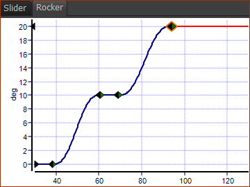 |
The new Motion Table is as follows. The Y-axis is the same.
The Slider-Cam and the Slot-Cam will now be the same as Method 3. |
|||||||||||||||||||||
