Ball-Joint
See: Add Ball-Joint. Tutorial 12: Design a Spatial Mechanism
Use the Ball-Joint for spatial mechanisms.
You must add a Ball-Joint to each end of one Part.
Connecting-Part : the derived name of a Part that has a Ball-Joint at each end.
One of the two Ball-Joint joins the Connecting-Part to a Part (frequently, a Motion-Part) in a different Mechanism-Editor.
The other Ball-Joint, at the other end of the Connecting-Part, joins it to a Part in the active Mechanism-Editor.
How to open the Ball-Joint dialog
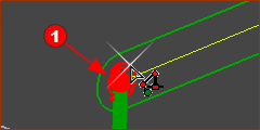 |
There are two Ball-Joints, with one at each end of a Connecting-Part. The Ball-Joint element symbol may be “inside” the symbol of the Connecting-Part.
The Ball-Joint dialog is now open. |
|
 Ball-Joint in the Selection-Window |
Ball-Joint dialog
 Ball-Joint dialog |
Ball Diameter
Ball Offset (±)
Ball Mass
|
|||
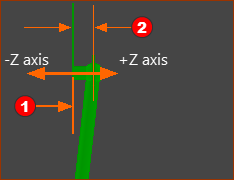 |
Example of Ball-Offset : Z = 10mm <<< the image shows the model from the left view - View toolbar > View Left (Shortcut : F7).
|
|||
When to use the Ball-Offset parameter? The symbols of all other Kinematic elements are on the Mechanism-Plane. However, the center of a Ball-Joint is frequently not on the Mechanism-Plane. The kinematic-analysis is correct only when the distance to the center of the Ball-Joint from the Mechanism-Plane is also correct. See also: Ball-Joint Configurations |
||||