Add Ball-Joint

<< Click to Display Table of Contents >>

Navigation:  MechDesigner Reference & User Interface > 2.2 Mechanism-Editor: > Kinematic elements >

Add Ball-Joint

Ball-Joint

Pin-Joints in MechDesigner

2x Ball-Joints in MechDesigner

Rod-End Bearing

Rod-End Bearing

2 x Ball-Joint in SOLIDWORKS

2 x Ball-Joint in
SOLIDWORKS

Terminology:

Ball-Joint :

A Ball-Joint makes a Point in a Connecting-Part coincident with a Point in a different Part.

You must add 2 x Ball-Joints to add a Ball-Joint to each end of a Connecting-Part :

1 x Ball-Joint between Points in different Parts that are in the active Mechanism-Editor.

1 x Ball-Joint between Points in different Parts that are in different Mechanism-Editors.

Spherical-Joint :

The kinematic and equivalent term for a Ball-Joint.

Kinematics-Tree :

Joints in a Dyad use the letter S for a Ball-Joint. For example, the R-S-S and P-S-S Dyads.

Derived Names:

Connecting-Part :

A Part with a Ball-Joint at its start-Point and at its end-Point

Part that is Completely-Free :

A Part with 3 degrees-of-freedom (no joints)

Part that is Free :

A Part with 1 or 2 degrees-of-freedom

See also: Ball-Joint dialog, Connecting Part Length and Diameter.

See also Ball-Joint configurations


Preparation

A typical preparation:

A typical prerpation for Add Ball-Joint

A typical prerpation for Add Ball-Joint

Mechanism A

Usually, Mechanism A is perpendicular() to Mechanism B

Part Red-14-3 in a kinematic-chain that is kinematically-defined in the image is Pink

Mechanism B - the active Mechanism-Editor

Three Parts:

1 × Part. It is kinematically-defined - typically the Base-Part.

2 × PartsRed-14-4Red-14-5. These Parts are not kinematically-defined.

Part Red-14-4 : A Part that is free. It is joined to the Base-Part with a Pin-Joint.

Part Red-14-5 : A Part that is Completely Free . It does not have joints before you do Add Ball-Joint.

Notes:

The Mechanism-Editors cannot be parallel to each other. They are most often perpendicular() to each other.

The Part that is Completely-FreeRed-14-5 will joint to Parts Red-14-4 and to Red-14-3 with Ball-Joints - these are two(2) S joints in the S-S-R or S-S-P dyads. S is for Spherical-Joint.

As you add the Part that is Completely-Free, try to estimate its length.

If it is too short or too long, the Ball-Joints cannot join it to PartRed-14-4 and PartRed-14-3 - you do not get the expected result.

Add Ball-Joint × two(2)

Do Add Ball-Joint two(2) times. One time to each end of the Completely Free Part.

MD-BALL-JOINT-PREP-B

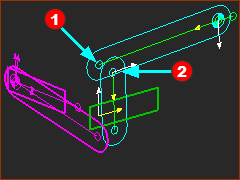
STEP 1: Start the Add Ball-Joint command

Add Ball-Joint icon

Add menu > Mechanism sub-menu > Add Ball-Joint

OR

Kinematic elements toolbar > Add Ball-Joint

STEP 2: Add Ball-Joint #1

Mechanism-Editor B is active.

1.Click PointRed-14-1b at the end of the Part that is Completely-Free

2.Click PointRed-14-2 at the end of the Part that is Free.

If you cannot select the two(2) Points to add a Ball-Joint, disable the Auto-Update tool, and try again.

When you do Add Ball-Joint #1 you can see the Ball-Joint symbol.

However, PointsRed-14-1bRed-14-2 do not snap together before you do Add Ball-Joint #2


MD-BALL-JOINT-PREP-C
MD-BALL-JOINT-PREP-D

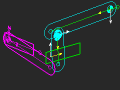
STEP 3: Add Ball-Joint #2
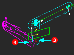
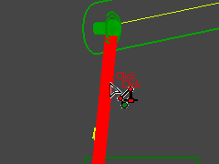
1.Click PointRed-14-3 at the other end of the Part that is Completely-Free

2.Click PointRed-14-4 - the Pink Point - at the end of the Part that is kinematically-defined in Mechanism-Editor(A)

Result

The Ball-JointsRed-14-6Red-14-7 snap to the Points in Mechanisms A and B.

The Parts that were Completely-Free and Free are now kinematically-definedRed-14-5Red-14-8


If the arrangement of the Parts that were Completely-Free and Free is not correct, then see Change-Dyad Closure
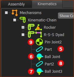
MD-BALL-JOINT-PREP-E
MD-KT-AddBallJoint

Kinematics-Tree

In the Kinematics-Tree,

There is a new Dyad - the R-S-S dyad.

The three Joints in the Dyad are:

Pin-JointRed-14-9 is the R joint - R is for Revolute-Joint

Ball-JointsRed-14-6Red-14-7 are the S Joints - S is for Spherical-Joint


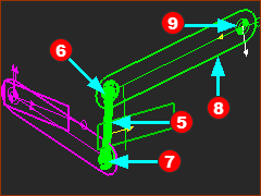
Connecting-Part: Edit Length, Rod Diameter, Ball-Diameter

Notes:

You cannot add Solids to Connecting-Parts.

MD-GA-BallJoint-EditConnectingPart

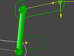
To edit the Length of the Connecting-Part
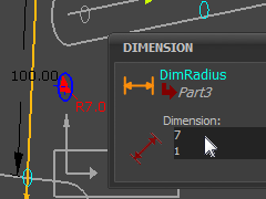
1.Mechanism-Editor: Double-click the symbol for the Connecting-Part

It is now open in the Part-Editor.

2.Part-Editor: Edit the Length dimension of the Connecting-Part

3.Exit the Part-Editor


To edit the Symbolic Radius of the Connecting-Part

1.Mechanism-Editor: Double-click the symbol for the Connecting-Part

It is now open in the Part-Editor.

2.Part-Editor: Add a Line or Circle

3.Part-Editor: Add a dimension to the Line or Circle

4.Exit the Part-Editor

The dimension becomes the Radius of the Connecting-Part.


To edit the symbolic diameter of the Ball-Joint - see Ball-Joint dialog


Notes:

In the Part-Editor, when the view is not the Front View, the CAD-Line, Axes, sketch-elements and dimensions may show in unusual places!

If you cannot add or edit a dimension: do View toolbar > Front Plane.

Also, to see the new Symbolic Radius: enable Visibility toolbar > Show Solids in Mechanisms

MD-GA-BallJoint-EditConnectingPart-Dim
MD-GA-BallJoint-EditConnectingPart-Show