Magnetic-Joint
Terminology
Magnetic-Joint : |
A Magnetic-Joint pulls a circular Profile to be in continuous contact with an irregular Profile (or Curve). The circular Profile and irregular Profile (or Curve) are in different kinematic-chains. After you add a Magnetic-Joint, the motion of the two kinematic-chains are related by the contact between the circular and irregular profiles (or curve). |
Irregular Shape : |
The Irregular Shape can be Profile from a sketch-loop, or a Curve that we calculate from a Point-Cloud. |
Point-Cloud : |
X-Y or R-Θ coordinates. Use a Point-Cloud FB to import the Point-Cloud coordinates. |
Curve : |
The smooth shape that we calculate for you from the Point-Cloud coordinates - see Point-Cloud dialog. |
How to open the Magnetic-Joint dialog
See also: Add Magnetic-Joint.
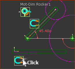 |
To edit a Magnetic-Joint:
|
||
Note: There are three states for the Magnetic-Joint icon in the graphics-area. |
|||
|
Magnetic-Joint is enabled and we find a solution. |
||
|
Magnetic-Joint is enabled but we do not find a solution. |
||
|
Magnetic-Joint is disabled. |
||
Magnetic-Joint dialog
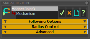 Magnetic-Joint dialog |
The Magnetic-Joint dialog has three separators: Following Options Radius Control Advanced |
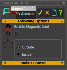 |
☑Enable Magnetic-Joint check-box The circular Profile is in continuous contact with the irregular Profile or Point-Cloud. ❑Disable Magnetic-Joint check-box The circular Profile will move to the Base-Value (Linear or Angular position) as specified by the Motion-Dimension FB that was in continuous contact with the irregular Profile. |
 |
Outside The circular Profile |
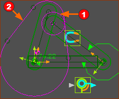 |
Inside The circular Profile
Note: The INSIDE option does not find a solution as successfully as the Outside option. |
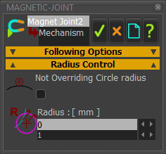 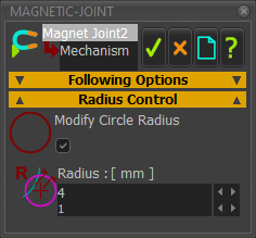 |
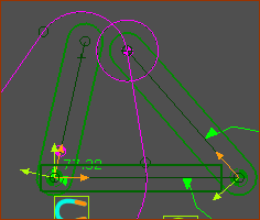
Optionally, edit the effective radius of the Circular Profile. ❑Not Overriding Circle Radius (default) ☑Modify Circle Radius For example: Radius = 0mm When the Radius is 0mm, the center of the Circular Profile moves along the Irregular Profile as normal. Radius = 3mm When the Radius is 3mm (for example), the center of the Circular Profile is 3mm inside the Irregular Profile. This is useful if you use a CMM machine with a probe diameter that is different to the Follower-Roller, and the CMM software does not have Probe Compensation. When the CMM data does not compensate for the Probe Diameter, you would enable Modify Cycle Radius to recreate the contact between the irregular-Profile and the Follower-Roller. Offset Profile Radius = Radius of Actual Follower-Roller – Radius of CMM Probe R = Rcf – Rp Rcf = Follower-Roller Radius; Rp = CMM Probe Radius. |
 |
| Advanced (with Notes) |
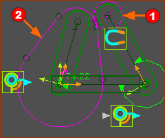
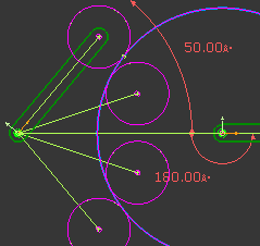 4 Possible Contact Solutions between Circular-Profile and a simple Irregular-Profile |
Notes: When you add a Magnetic-Joint, we use numerical techniques to find the point of contact between the Circular Profile and Irregular Profile. To humans, it is easy to see the contact that you want. But mathematically, even when the Irregular-Profile is a simple shape, there are usually a minimum of 4 solutions - see image to the left. MechDesigner may find the solution you want, or a solution you do not want, or even fail to find a solution at all. BEFORE you enable the the MAGNETIC-JOINT, edit the starting position of the Circular Profile to be less than 0.5 x Radius of Circular-Profile from the Irregular-Profile - and ideally even nearer. To edit the starting position of the Circular-Profile
We use the factors in Advanced to use find the solution you want. Reset Range Factor (default = 2) This factor limits the range of values within which to search for a solution for the Motion-Dimension, when the model is at the Home position (MMA = 0). A Reset Range Factor = 1 is equal to the 1 × Radius of the Circular Profile. The smaller Reset Range Factor, the nearer you should edit the Base-Value to put the Circular Profile to the Irregular-Profile before you enable the Magnetic-Joint. Running Range Factor (Default = 1) MechDesigner must find the contact-point between the Circular and Irregular-Profiles at all steps in the machine-cycle. There are frequently at least 4 solutions - see image above. The solution at any step in the machine-cycle should not be very far from the previous solution. Use the Running Range Factor to limit the range of Motion-Dimension values within which to search for a solution from the previous solution, at each step of the solution cycle. Running Range Factor = 1 is equivalent to 1 × Radius of Circular-Profile Reduce the Running Range Factor if the Circular-Profile does not remain in contact with the Irregular-Profile, as you step through the machine cycle. |
|
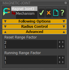 Magnetic-Joiont dialog |