Continuous-Crank
See also Add Continuous-Crank
Usually, in a multi-part mechanism, you design the motion for a Tool-Part (the Part with the tooling), and we use Inverse-Kinematics to calculate the motion of a follower or a servomotor. The follower usually oscillates or reciprocates. A servomotor may also oscillate. However, there is also the case in which the servomotor rotates completely, but with a non-uniform rotating speed. This is a special-case. To enable this special-case, the rotating part must be the correct length, and its motion, also derived by inverse-kinematics from the motion of the Tool-Part, is more complex. This is one application of the Continuous-Crank FB. |
How to open the Continuous-Crank FB dialog
|
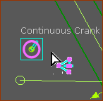
Edit the Continuous-Crank FB:
|
The Continuous-Crank dialog is now open.
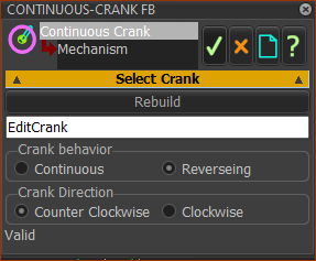
Continuous-Crank dialog
 Continuous-Crank dialog - not enabled |
STEP 1: Select Crank Behavior and Direction Crank Behavior
Crank Direction
|
|||||||||||
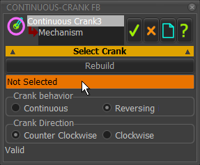
 Continuous-Crank dialog- enabled |
STEP 2: Activate the Not Selected box
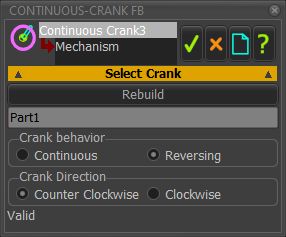
STEP 3: Click a Part that you want to be the Continuous-Crank
The Part immediately changes its length so that it can rotate continuously or oscillate by 180º. If there is a problem, see Messages at the bottom of the dialog. STEP 4: Confirm the behavior is as expected
STEP 5: Click Messages at the bottom of the dialog: When you select a Part as the Continuous Crank, there is be a message at the bottom of the dialog.
|
|||||||||||
 Continous-Crank dialog |
