Design-Set FB
See Add Design-Set
Use Design-Sets to edit in one place dimensions and parameters that you believe to be important to the outcome of a design-objective.
You can add more than one Design-Set to model for different design objectives.
Question:
Why use a Design-Set?
Answers:
A.Frequently, to improve a design objective, you must edit the same dimensions and dialog parameters many times. With a Design-Set, you can add and edit them in one dialog.
B.If you need to open the model after a period of time, a Design-Set reminds you of the dimensions and parameters that are important to your design. Also, you can give your model to different engineers and tell them to ONLY edit the dimensions and parameters that are in the Design-Set.
C.When a dimension is in a Design-Set, you can only edit it in the Design-Set. This protects the dimension from you accidentally editing it in the Part-Editor.
IMPORTANT
After you add a dimension to a Design-Set, you CAN ONLY use the Design-Set to edit that dimension. To edit the dimension in the Part-Editor again, you must delete the dimension from the Design-Set. Note: A dimension that is is gray in the Part-Editor indicates you cannot edit it. |
Top-Tips:
1.Rename the Dimensions you add to a Designs-Set to remind you of its function. 2.Rename each Design-Set to remind of its design-objective. |
|
To open the Design-Set dialog
|
|
|---|---|---|
The Design-Set dialog is now open. |
||
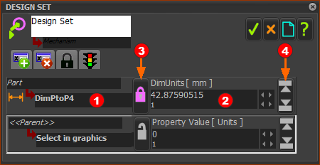
Design-Set dialog
 Design-Set dialog - LOCKED  Design-Set dialog - UNLOCKED |
||
When you open the Design-Set dialog, the toolbar is locked. It is NOT active. The Design-Set toolbar icons - when active - are:
To enable the Design-Set toolbar icons
The icons in the toolbar are colorized and the Design-Set interface is active. |
 Design-Set - 2 Element Rows |
|||
To add Element-Rows
The active Element-Row.
To delete an Element-Row
|
 |
|
|
Maximum and Minimum 'Hard-Limits' It is frequently useful to set maximum and minimum limits for each dimension or parameter in the Design-Set. 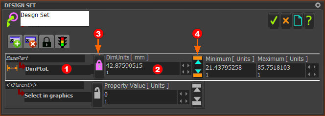 |
|
To edit the Maximum and Minimum limits:
|
To replace a Dimension or Parameter in an Element-Row with a different Dimension or Parameter.
|
Parameter Lists in different Element-Types:
In addition to dimensions, you can link parameters from dialogs for different element types to a Design-Set.
For example: Parameters of FBs, Parameters of a Gear-Pair, Parameters of a CAD-Line, and other elements.
 Link a Parameter (from a dialog-box) with an Element-Row
Select the Element-Type:
If the Element-Type has only one(1) Parameter
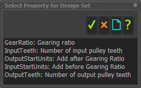
If the Element-Type has two(2) or more Parameters:
|
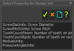
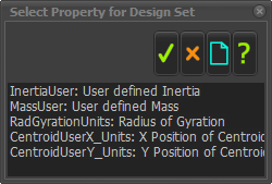
Available Element-Types and their Parameters
When you click a Linear Motion FB, you add: •Linear Motion as the Element Name •OutputStart_Units as the parameter. OutputStart_Units ≡ Start-Angle parameter in the Linear-Motion dialog. |
When you click a Motion-Dimension FB, you add: Mot-Dim Rocker (or Slider) as the Element Name BaseUnits as the parameter. BaseUnits ≡ Base-Value in the Motion-Dimension dialog. |
 |
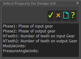 Do not select Phase1 or Phase2 for the Design-Set. |
 |
| CAD-Line |
 |
| Pulley |
When you click a Pulley, you add •Path Joint as the Element Name •Tooth-Count as the parameter. Tooth-count ≡ number of Pulley teeth parameter in the Pulley dialog. |